Studebaker V8
When chasing parts for the Studebaker 232 engine, you'll conclude items like pistons and rings are almost unavailable. Don’t dismay, all the 259
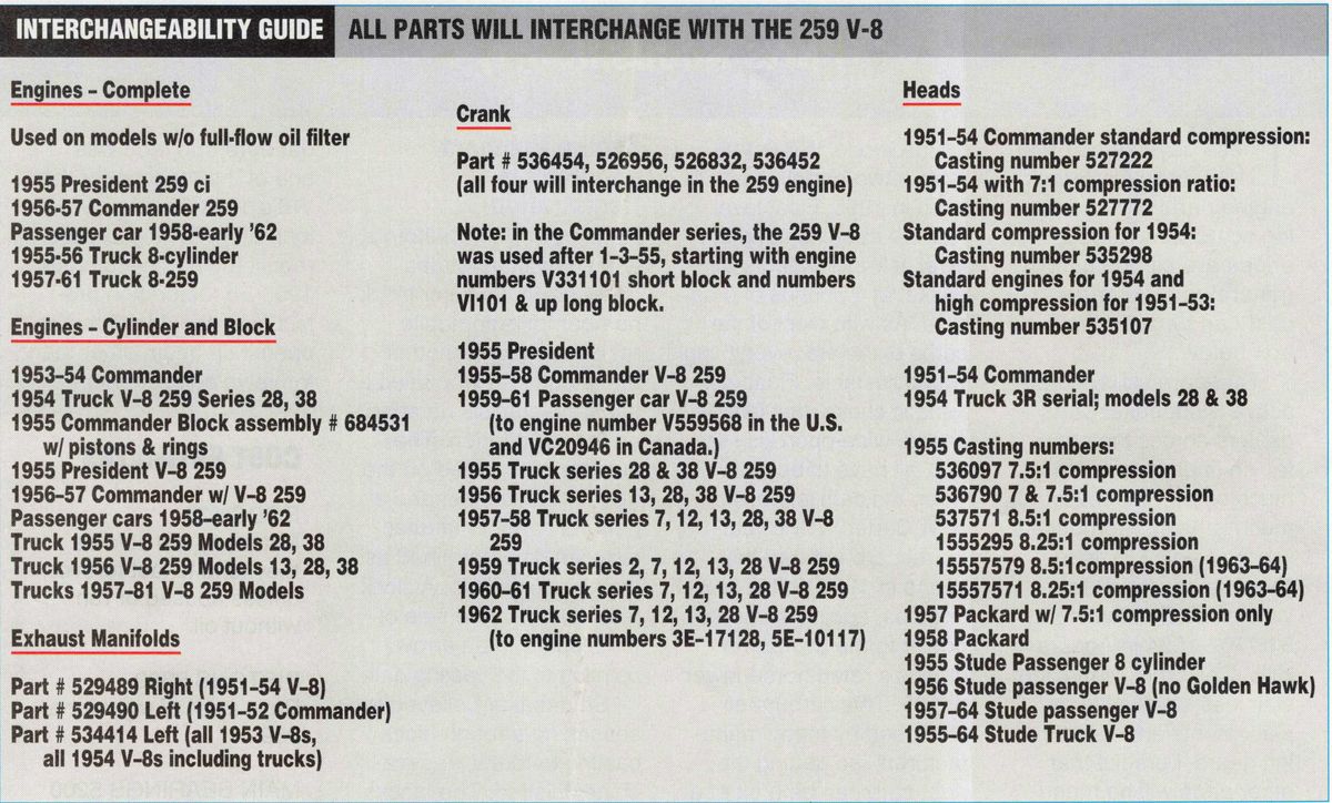
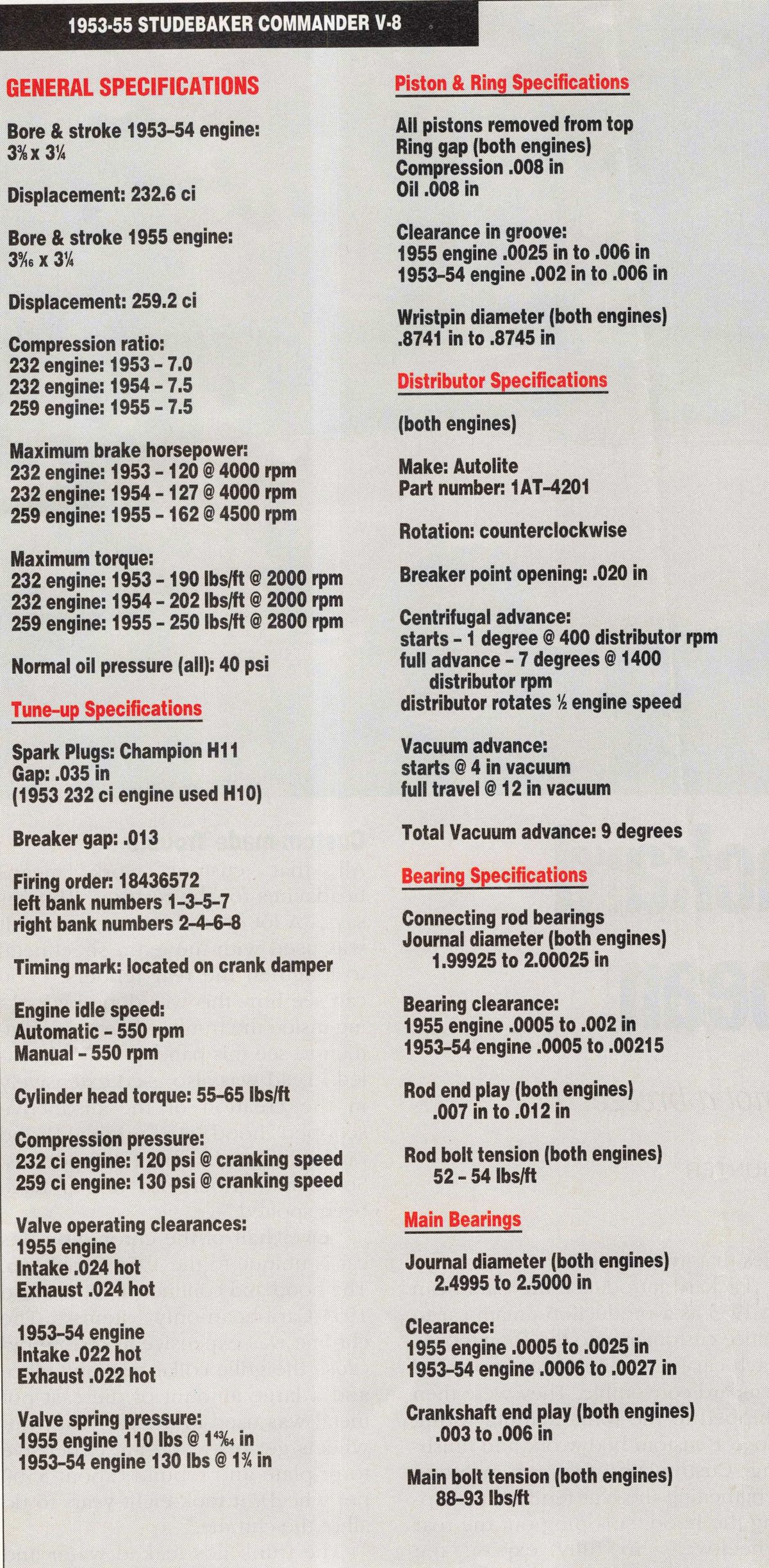
Te first engine in our series is the Studebaker Commander V-8 in its 232.6-cubic-inch and 259.2-cubic-inch editions. The 232 was installed in all Commanders from 1951 until 1954. The 1955 Commanders had the 259 (except for a few — built before January 3, 1955 — that had a 224.3-cubic-inch engine). The 259 was also loaded into the 1955 President models, and could also be found in later-model Commanders, Hawks and Larks. See the _ interchangability chart for more details.
The 1955 Commander, coupe or sedan, was advertised with a “thrillpacked” 140 horsepower provided by the 232-cubic-inch engine. However, the 259 was rated at 162 horsepower, which coincidentally was the same figure that Ford claimed with its 272-cubic-inch engine and Chevy claimed with its 265.
Parts — crank, rods, pistons, and bearings will interchange with the 232. When it comes to rebuilds, most people choose to bore the 232 to the 259. From the outside, determining the difference between the 232 and the 259 is almost impossible. Inside the difference is essentially the bore: 3% inch for the 232 and 3%6inch for the 259. The heads for both engines were a wedge design with a small dome cast into it for better flame propagation. Valves are unique to Studebaker. In refacing the original valves, care must be taken to only take off the minimum to clean up the valve faces. Seat width after grinding will measure Minch to %:-inch according to operating specifications.
In the 1950s, “thin-wall” castings became popular with the big manufacturers. Studebaker, however, elected to go with a heavy casting that could accept large overbores. Building a 259 out of a 232 is simply a matter of boring the cylinders out to a 3%o-inch diameter or an overbore of .187. Furthermore, the 259 cylinder walls easily accommodated overbores up to .120-inch. I’ve seen one engine — a cutaway in the Studebaker museum — that went to a .156-inch overbore. Even with that much overbore, the walls were still about as thick as a
Chevy thin-wall block. I would recommend never going beyond .120-inch on the 259 to ensure block integrity.
Rebuild Problems
According to the experts at Studebaker West in Redwood City, California (415/366-8787), these engines are commonly found with 100,000 miles on them before the original steel rings wore out and the engine began smoking like a diesel. Oil consumption problems dictated a rebuild more than any other single problem. Abuse or neglect were the common reasons behind an engine failure. A word to the wise, check the oil at least once a week if you drive the car frequently, and before every drive if the car is only used for special events. Certainly any vehicle of this vintage requires that much attention.
One 259-cubic-inch engine I saw had three- and four-piece rods with the bearings welded to the crank. This condition was brought about by an owner who was driving the car to the shop for an engine rebuild, but he neglected to check the oil before leaving on the 30-mile trip. The car made 25 of the 30 miles before loud (and coincidentally expensive) noises came from under the hood. In quick fashion the Studebaker ground to a halt. The pros at the shop estimated about three tablespoons of oil were left in the pan. Two thousand dollars later the engine ran again.
Engine Design The original 232-cubic-inch V-8 was designed in 1951 with the idea of having it grow as the years went by. By increasing the stroke to 3%-inch, engine displacement topped out at 289 cubic-inches 1956. With the optional 4-barrel Carter WCFB carburetor and a 7.80 compression ratio, the 289-version put out 210 horsepower at 4500 rpm.
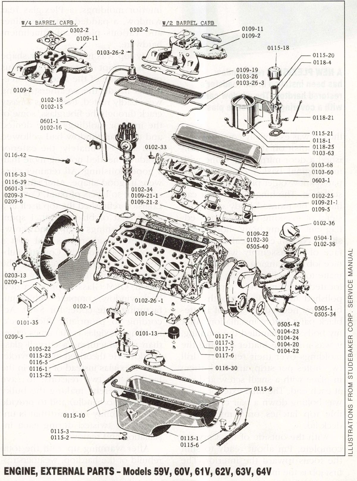
The block was designed to have a full-pressure oil lubrication system like the Cadillac 331-cubic-inch overhead valve V-8. The Chevrolets of this vintage still used oil dippers on the bottom of its six-cylinder rods to provide lubrication. Another Studebaker feature was the use of timing gears between the crank and cam instead of the common gear set and chain most other manufacturers used. To correctly time the Studebaker, the gears had to be aligned so that the two “0” marks on the crank-gear split the single zero on the cam-gear. Always time the cam to the intake stroke. If you don’t, it is possible to set the gear off by 180 degrees, which will result in a lot of backfiring but little else. Due to a rugged design, these gears, coupled with solid lifters, made for engine longevity, although the valves had to be set at regular intervals. A good approach is to adjust the valves 500 miles after a rebuild and at 15,000-mile intervals after that. (if you aren’t going to get. to the 15,000-mile interval for many years, check the valves at major tune-up time.) Pistons were the full-skirt design with two compression rings and one oil-control ring. To assemble them on the rods, it may be necessary to heat the piston in a 225-degree oven and freeze the wrist pin for 30 minutes each so clearances will open enough to let the pin slide through the piston. When replacing the gaskets on the oil pan, one particular detail stands out. There is a filler block, shaped in a half circle, that has to be removed for proper installation of the oil pan side-gaskets. Four screws hold the filler block to the front of the engine block. The oil pan fits over the filler block with a gasket between the pan and filler block.
Adjusting the Valves Valve adjustment is done by fully warming up the engine, then removing the valve covers and positioning the spark-plug-wire brackets on the rocker-arm assembly screws. Then, with the engine idling, set the valve clearances. The adjusting screw is found under the rocker arm on the pushrod side. Setting the valves takes a little practice, and can blow oil around a bit, but after doing it once or twice, you get pretty fast at turning the wrench. Only remove one rocker cover at a time to help keep the mess down. The feeler gauge should have a slight pull as it slides between the valve and the rocker.


