
A New Way To Wire Your Ride
Installing Wiring Has Always Taken a Lot of Time and Effort. This Computerized System Helps to Simplify Things.
WHEN IT COMES to putting a project car back together, installing the wiring system is often the most dreaded aspect of that endeavor.
Original wiring systems are aged, wires are often broken, none of them are labeled and, worst of all, someone has most likely been there before you and added to or removed some very important part of the system. Installation can become a nightmare.
Then there are the “off-the-shelf” wiring systems. These wiring harnesses allow you to scrap the old stuff and start with new, but you are still working with lots of wire and that doesn’t do much to stop the hair-pulling.
Granted, I have used off-the-shelf systems extensively in the past and they work great for what they are, huge masses of wires. A good example is Project ’46. Recall the one-inch-thick bundle of wires I routed through the console? While each and every one of those wires was labeled and color coded, I still had that huge mass of wiring to deal with, and that was just the wiring for the rear of the car.
A New Way to Wire
Now let’s move into the 21st Century and consider a system that doesn’t use pounds and pounds and miles and miles of copper wire. Instead, this system incorporates the use of computerized power modules to distribute power out to the various components in your car, sometimes with a single wire instead of a bundle of 20. How’s that for reducing the amount of wire needed to plumb your ride?
Of course, the question has to be, who has such a system, what is it called, how does it work, and why do I need it?
To answer that, ISIS Power has the system, it is called the ISIS™ Intelligent Multiplex System, it works by employing a plug-and-play modular, computerized power distribution system that reduces the amount of wiring needed to wire your ride, and you need it because it cuts installation time by more than half, is designed to survive automotive environments, uses low voltage, low current outputs, and eliminates the need for routing miles and miles of copper wire.
I know what you are thinking. Computers in my vintage ride? No way. My old stuff just won’t work with computers. That’s what I thought, then I realized the only major change I would be making was in the reduction of wire used to route circuits from the firewall to the front and the rear of the car plus the elimination of a lot of relays, which, quite frankly, tend to present problems when wiring them anyway.
The Components
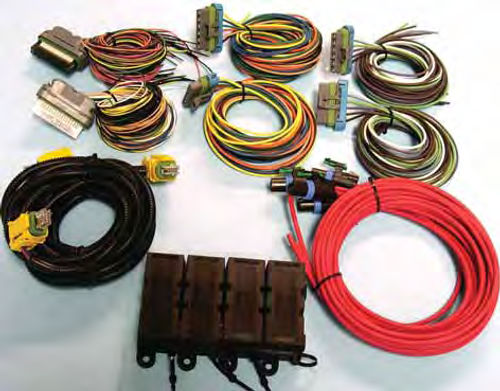
Believe it or not, this is the guts of the basic three-cell ISIS™ Intelligent Multiplexing system (Photo 1). It consists of one Mastercell input unit, with up to 50 separate inputs, and two Powercell control units with 10 outputs each.
Fifty inputs means the capability of handling up to 50 different circuits. That’s a lot of circuits.
I would think that if you need more than 50 circuits to wire your ride, you may be over-plumbing the vehicle.
Ten outputs per Powercell gives you a total of 20 circuits with which to work. Very few cars will ever need more than 20 circuits, but should that issue arise, the Mastercell with its 50 input capability will allow you to gang up to five separate Power Cells together to give you all the circuits you could ever want.
Just like old-style wiring harnesses, the components must be connected together. In this case, the Mastercell unit is connected to the Powercell units and the Power Cells are connected to the various components in the car.
To do that the kit also includes, from left to right and top to bottom in Photo 2, two input harnesses for the Mastercell, four output harnesses for the Power Cells, one CAN cable, four power input cables, and one, four-fuse battery protection kit called the MEGA™ Fuse Kit.
Also included but not shown are two dummy power connectors, one dummy input connector, one dummy CAN connector, and a ton of wire connectors and terminals. One thing you should note here is the absence of the huge mass of wires common to the old-style systems. It isn’t needed.
What are the dummy connectors used for? Most vehicles won’t need the full 50- circuit potential of the ISIS™ system. The dummy connectors allow you to cap the unused connections on the individual modules instead of using the wired connectors that would leave you with extra wire to deal with.
The Hook-Up
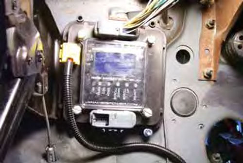
Just like when you’re wiring a ride the old, hard way, everything starts under the dash. But instead of installing a fuse block with a huge bundle of wires sticking out of it, the ISIS™ Mastercell input unit takes its place. This unit is bolted to the firewall in a vertical position, much like the old fuse block would have been installed (Photo 3).
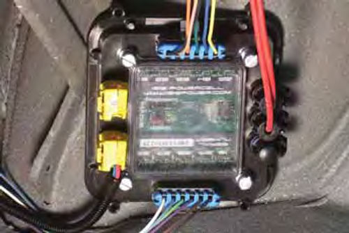
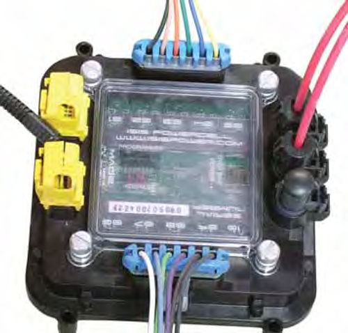
Next are the Powercell control units. These units also need to be bolted securely and vertically, if possible. But instead of being mounted under the dash, one is mounted in the engine compartment, maybe on the firewall or core support, where it will be near a cluster of electrical components, while the other unit gets bolted somewhere inside the trunk, again, near components such as the taillights (Photo 4).
The main thing to understand here is to mount all three units vertically, if possible, to help optimize airflow around the units. Attach the units to flat surfaces using one-inch long, quarter-inch sheet metal screws in the four mounting holes. Also take into consideration the length of the CAN cable. The system can’t work if the CAN cable can’t be stretched from the Mastercell to the Power Cells.
Don’t worry about the heat; the Mastercell is capable of withstanding temperatures of 120° F. That’s good for anywhere inside the car or inside the trunk.
The Powercell units are rated to withstand temperatures up to 250° F. That’s on a firewall, fender skirt, core support or anywhere inside the trunk.
Since I’ve mentioned routing it, let me briefly explain the CAN cable. CAN is a computer guru term for Controller Area Network bus cable. This cable is used to connect the three units together and is the means by which the Mastercell communicates with the Power Cells to let them know which circuit or circuits to turn on or off.
Doing the Wiring
I’ll start with the Mastercell. When you purchase the three-cell starter kit, it will come with a nicely detailed instruction manual. Inside that manual is a breakdown of the pre-configured wiring components. For example, to wire the headlights you need two separate wires coming from the Mastercell, one to tell the forward Powercell to illuminate the low beams via one wire, and another wire to tell the forward Powercell to illuminate the high beams.
The two headlight wires coming from the Mastercell are connected to the dimmer switch (I’ll explain that with an illustration a little further down), and the two corresponding wires at the forward Powercell are connected to the high and low beam sides of the headlights. It’s that simple, but there is the issue of the real world and that requires a little explaining.
I have to start by telling you that most of what you know about wiring cars the old, hard way doesn’t apply here. That’s because the Mastercell works off of a grounding principle to send a low voltage signal to the Powercell, via the CAN cable, to turn on or turn off a particular circuit.
This is important. At no time should you ever apply 12 volts of power to the Mastercell. Doing so will destroy the unit. Only the Powercell units receive 12 volts of input, which I’ll explain later. Keep this principle in mind at all times and you will be all right.
To help you better understand how this system works, I’ll go through the steps to wire the headlights. In the process, you’ll see how drastically this system differs from the old way of wiring.
To start with, your old wiring harness needed 12 volts applied to the 12-volt input terminal on the headlight switch to make the headlights, taillights, park lights, dash lights and interior lights illuminate.
On the old wiring system, power came from the battery via the “B” terminal on the ignition switch, over to the headlight switch, and that power was delivered out to the lights when the switch was activated (pulled).
With the ISIS™ unit, making the headlights come on is a matter of routing one of the black ground wires on the Mastercell to the 12-volt power input terminal of the headlight switch. (See Illustration 1.) Yes, this is the same terminal the old wiring system would have connected straight to the “B” terminal on the ignition switch. Remember, this is the new way. Do not attach 12-volt power to this terminal.
To make the headlight low beams come on, the Mastercell uses a white wire with a green tracer, as indicated in the manual, to detect the completed grounding circuit when the headlight switch is pulled to the ON position.
Notice in Illustration 1 this wire is connected to the low beam side of the dimmer switch. Also notice in the illustration that an 18-gauge wire is still needed to go from the power input side of the dimmer switch up to the headlight output terminal on the headlight switch. This wire was always needed, even with the old school wiring system.
When wired the new way, we now have a series grounding circuit that goes from the ground wire on the Mastercell, through the headlight switch, to the low beam side of the dimmer switch, and back to the Mastercell via the white wire with the green tracer. When the headlight switch is pulled to turn on the headlights, this low-voltage circuit is complete.
That completed circuit sends a signal through the Mastercell and out to the forward Powercell via the CAN cable telling this unit to turn on the low beam headlights. And how does that work?
Each Powercell has two 12-volt power connector cables to bring power into the unit. (I’ll talk about where that power comes from later.) Since we are working with the headlights, we are using the forward Powercell. This unit has a white wire, indicated in the manual as being the low beam power wire, that is connected to the low beam wires of the headlight connector plugs (Illustration 2).
When the Powercell receives the signal from the Mastercell to turn on the low beam headlights, 12 volts of power moves through the Powercell and out to the headlights making the low beam side of the headlights illuminate. The headlights are still grounded via the normal black wire ground.
I have to tell you, I really had to work on getting my brain to make the shift from 12-volt powered switches to series grounded switches, but once my brain made the switch, wiring became easy again.
Since we’re thinking headlights, let’s move to the high beam mode. The Mastercell unit uses a blue wire with a red tracer, indicated in the manual, to activate the high beam signal. You got it, this wire attaches to the high beam side of the dimmer switch, as shown in Illustration 1, so that when the dimmer switch is shifted from low beam to high beam a signal is sent to the forward Powercell where a blue wire, indicated in the manual as the high beam power wire, is then routed out to the high beam side of the headlights. (Shown in Illustration 2.)
Is this better than the old way? Consider that the original harness would have required two wires passing through the firewall and out to the headlights to make those lights work. Now we have none. Add to that the wires needed to illuminate the park lights and turn signals, operate the starter or sound the horn, and suddenly you have a small bundle of wires to contend with. With the ISIS™ unit, all you have is the CAN cable.
Since I’ve mentioned the park lights and the turn signals, let’s see about connecting those. I’ll start with the park lights and use the GM-style headlight switch shown in Illustration 1 to demonstrate how the park lights are wired.
The park lights use two separate terminals on the back of the headlight switch. One provides 12 volts input, the other 12 volts output to the lights themselves. Twelve volts in and twelve volts out? Yes, this is how the old school wiring system provided power to the park lights without having to turn on the headlights.
Referring to the manual I know that the blue wire with a black tracer on the Mastercell has been pre-configured for the park lights. This wire is connected to the park light output terminal on the headlight switch. Since the park lights have their own power input terminal (old school wiring system) a second black grounding wire from the Mastercell is connected to that terminal.
When the headlight switch is pulled to the park light position, the series grounding circuit is complete and a low voltage signal is sent from the Mastercell to the forward Powercell telling this unit to turn on the park lights via the yellow wire routed from the Powercell to the park lights (Illustration 2).
The taillights are a little more complicated as the rear Powercell doesn’t have a pre-configured output for the taillights. (ISIS Power is working on this issue and the system you purchase may already have a dedicated wire on the Mastercell.) To get around this, I connected an “open” Mastercell output wire (for example the white wire with a black tracer) to the tail light terminal on the headlight switch and used the corresponding output wire on the rear Powercell, a light blue wire, as indicated in the manual, to illuminate the taillights anytime the headlights or parking lights are turned on.
And what’s this “open” output I mentioned? All three cells are configured with “open” circuits. For example, the white wire with the black tracer on the Mastercell is an “open” circuit. If I take this wire and touch it to any of the black ground wires on the Mastercell I now have a completed circuit and a signal is sent from the Mastercell out to the Powercell.
I already know from checking the manual that the “open” circuit with the white and black tracer wire on the Mastercell corresponds to the light blue wire on the rear Powercell. If I connect this wire to the taillights they will illuminate when the headlight switch is pulled to the Park or Headlight position.
This may sound a little complicated, but with the instruction manual in front of you to indicate which wire on the Mastercell corresponds to which wire on the Power Cells, this is really pretty simple. Remember, I like things to stay simple.
Now, For the Turn Signals…
Wiring a car the old way required the use of flashers to get the turn signal lights to blink. The ISIS unit is already programmed to allow the turn signal lights to blink when making a turn as well as to stay lit when the parking lights are on.
Wiring the turn signals isn’t much different from wiring the headlights or park lights with the main difference being the switch used to trigger the series grounding circuit for the Mastercell. In this instance, the switch is the turn signal switch in the steering column.
The output wires for the Mastercell are a yellow wire with a black tracer for the left turn signal and a yellow wire with a red tracer for the right turn signal.
If you’re using a GM-style column connector, the yellow/black wire connects to the M terminal on the plug, the yellow/red wire connects to the N terminal. The black ground wire from the Mastercell connects to the L terminal. That wire is the old school 12-volt power input terminal for the turn signals.
Ford would use a green/ white wire for the left turn and a white/blue wire for the right turn.
The corresponding wires on both the forward and rear Power Cells would be brown for left turn and violet for right turn. These wires connect to the “bright” element wire in the lamp sockets, usually a yellow or green wire.
Is all of this starting to sound familiar now? It should, all connections to the Mastercell form grounding loops; no power input is needed. All connections to the Power Cells provide the needed 12 volts going out to the attached components.
Now let’s get a little more complicated and wire the windshield wipers. First off, you won’t find a pre-configured terminal on the Mastercell for the windshield wipers so I’ll be using one of the “open” outputs on both the Mastercell and the forward Powercell.
Why no pre-configured terminal? The wiper switch is a high/low switch with the option of a washer button and since this is a very uncomplicated system the best way to wire this circuit is to route an “open” output wire from the Mastercell to the “I” terminal on the Ignition switch (this switch will already have a black ground wire from the Mastercell going to the “B” terminal on the Ignition switch from having previously wired the ignition switch) and wire the corresponding forward Powercell wire to the 12-volt input terminal on the wiper switch.
By routing one of the “open” circuit wires on the Mastercell to the ignition switch, a completed circuit happens any time the ignition switch is turned to the ON or ACC position. That, in turn, alerts the forward Powercell to provide power to the corresponding wire. That wire becomes the power input for the wiper switch. The wipers only come on if the wiper switch is turned on (Illustration 3).
Yes, this type of circuit also works great for the air conditioner, radio or anything else that comes with an incorporated or variable speed switch.
Providing Power to the Power Cells
This is so important that it deserves repeating, again. At no time should 12 volts of power be applied to any of the connections on the Mastercell. Power is delivered out to the electrical components through the Power Cells; thus the name.
The kit comes with four red power cables with each Powercell receiving two of the cables (Photo 5). The Power Cells will accept up to three cables, so be sure to cap the extra connectors with the provided sealing plugs.
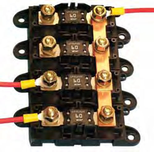
Also provided in the kit is the MEGA™ Fuse Kit (Photo 6). This is the means by which fused power is delivered from the battery to the Power Cells. Power from the battery is connected to the bus bar on one side of the Fuse Kit using one of the supplied red wires. Power is then delivered to the Power Cells by connecting the remaining red wires to the individual fused terminals on the other side of the unit. In a nut shell, power comes in at the bus bar and goes out via the fused terminals on the opposite side of the Fuse Kit.
You can connect the power input cables directly to the battery as I mentioned above, or to the “B” terminal on the starter. This is the best way to ensure a constant 12 volts of input power to the Power Cells.
The inLINK Remote Control Unit
With the system fully operational, all that is left to do is program the remote control unit. This unit looks just like the remote control hanging from your Toyota keychain. However, it is much, much more. There are four buttons on the unit. They are from top left to right bottom, security enable, security disable, trunk open, and park lights.
Note: Security doesn’t lock or unlock the vehicle. Security disables the ignition system so that the vehicle cannot be started. Trunk open does just that, opens the trunk, provided you have added a power trunk latch to your ride. The park light button can be very handy on a dark night in the Walmart parking lot. Just hit the button and the parking lights come on: Instant car locator.
If you click the small button on the right side of the remote you also have up to three more “pages” of options. For example, one press converts the buttons on the face of the unit to “page 2” and the buttons are then converted to ignition, as in remote start, four way flashers, fan override and panic switch.
What does the panic switch do? It makes the horn sound until the button is pressed a second time to turn it off.
Pages three and four allow you to program in accessories such as automatic door locks, interior lights, maybe a radio control, and even a power antenna, if desired.
The input channels for “pages” three and four are connected directly to “open” inputs on the Mastercell so you aren’t limited only to the accessories mentioned above. In fact, the “pages” are only limited by the number of accessories you decide your ride should have.
Signs of Normal Operation
With the ignition off and no electrical system components in operation, the LEDs in the Power Cells, find one at every circuit fuse, should be off.
A blue light located near the center of the Power Cells and the Mastercell should be blinking slowly, like a heartbeat.
The Insight, found on the Mastercell, should read “CANBUS STATUS—NORMAL.”
When a switch is activated, such as the headlight switch, the LED at the corresponding output fuse on the Powercell should turn on, letting you know that circuit is operating normally.
Is this the wave of the future? Yes. If you check under the hood of the higher end ride your wife drives to work everyday you will find an OEM version of this very set-up controlling many of the circuits inside the vehicle.
Will I switch from old school fuse blocks and copper wire to computer controlled wiring? I already have. Got a question on this or any other article I’ve written lately? Send it along.
Resources
ISIS Power
800 E. Northwest Highway
Des Plaines, IL 60016
LPL Body Works, LLC
5815Contented Lane
Amarillo, TX 79109


