
Installing a Modern Sequential Tail Light System
Cougars Are Known for Flicking Their “Tail” Lights, But With Passing Decades the System May Fail. This Electronic Setup Will Bring Back the Life to a Cougar’s Tail and a Mustang’s as Well.
The following restoration project was performed in our shop on a vintage Mercury Cougar, but the equipment used will work on any model vehicle with a 2- to 4-bulb tail light setup that you want to convert into a sequential turn signal system.
1. STOCK COUGARS were known for their sequential taillights and the customers want to keep them operational. We decided to convert this one to a new-style fully electronic system for more reliability compared to the old “dynamite sticks” used by Ford/Mercury in 1969. As seen here, Classic Design Concepts has a system for late model Mustangs to convert them. We will retrofit our car to handle this system.
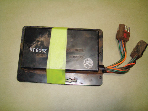
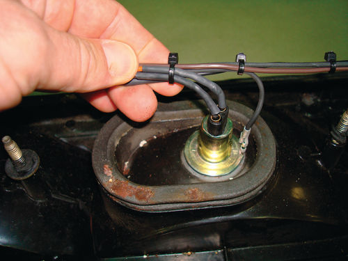
2. THIS IS the old brain that Mercury installed, and it is susceptible to failure after having been on the streets for more than four decades, much like the old “dynamite sticks” that Ford/ Mercury first installed in Shelbys and Cougars. The new kit, on the other hand, comes with small modules that Ford made for 2005 to 2009 Mustangs. Might as well accept it, it’s a Digital World we live in.
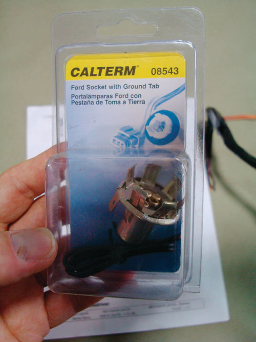
3. WE START with brand-new sockets to install new bulbs into our taillight housing. Calterm manufactures this unit but many companies have them. A little tweaking and they will fit your Ford housings.
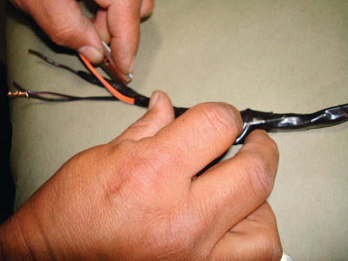
4. LOUIE TRIMS back the wiring on the pigtails on the new sockets.
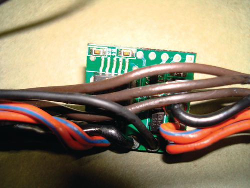
5. AS SEEN, the Classic Design Concepts sequential module is very small.

6. WE FLIP it over and you can see Mustang written on the module.
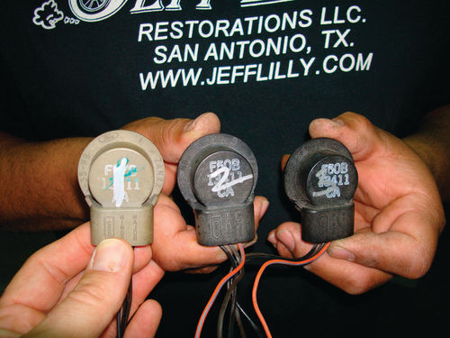
7. LOUIE MARKS the bulb sockets for the later-model Mustang from the kit so he can keep the inner, center and outer bulbs separate as far as the wiring is concerned.

8. HE FINISHED off the pigtails and gets ready to connect them by soldering the wiring to the modules.
9. SHRINK TAPE is installed over any splices.
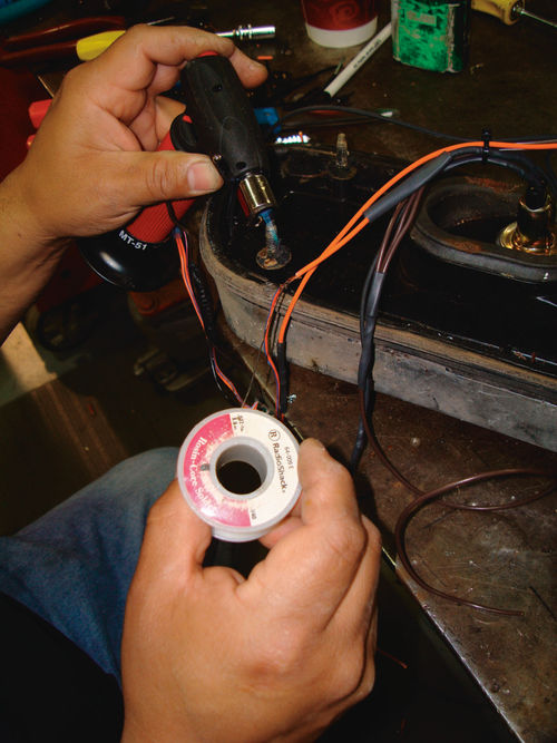
10.HE SOLDERS the #1 socket wire to the #1 module wire and proceeds on to the second and third lights until finished.
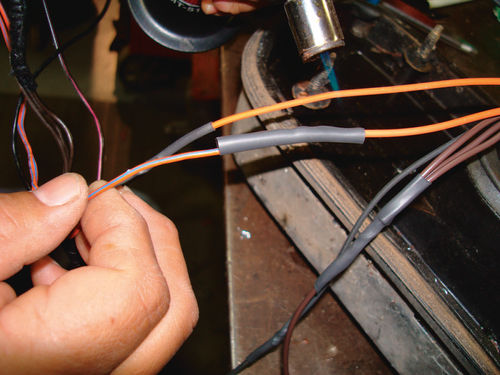
11.AS SEEN, he had slid some shrink tubing on the wire beforehand and has slid it down in place. He is now heating it with a baby piezo torch.
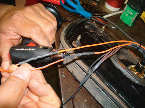
12.ONCE SHRUNK they really tighten on the wire which causes a permanent seal and provides necessary protection.
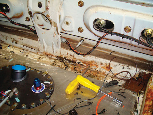
13.EVERYTHING IS installed and we are ready to fire up the turn signals.
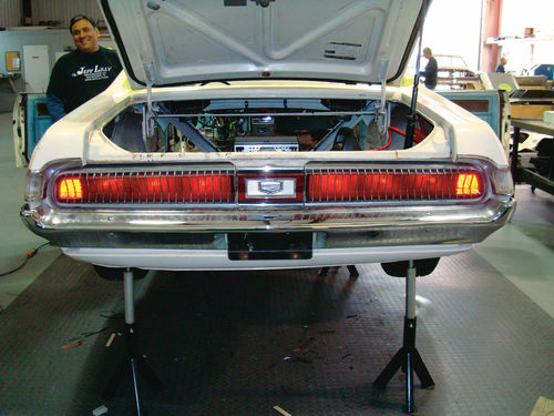
14.WE TURN on the lights and you can see that the running lights are operational.

15.THE FIRST light in the sequential series kicks off.
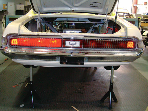
16.THE SECOND one hit and now the third one has as well. It is rather hard to shoot the system in operation with a camera but it does work individually or in sequential series on all three lights.
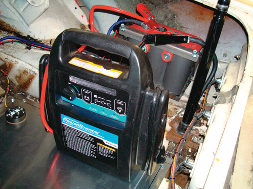
17.WE SIMPLY used a battery jump starter to power the system up during testing.
RESOURCES
Jeff Lilly Restorations, LLC
11125 F.M.1560 N
San Antonio, TX 78023
Classic Design Concepts
28266 Beck Road
Wixom, MI 48393


