
The Buildup Continues on Project 46
In the last installment I took care of a number of basic car building issues that had to be accomplished before I could get serious about assembling this ride. With those things out of the way, it’s time to complete the painting process and begin the final buildup. I’ll start by getting some color on the front sheet metal pieces.
The front end appears to consist of two fenders, a hood and a grille. But when you break the front end sheet metal section of this car down into individual pieces it actually consists of 10 parts: the hood, both fenders, two fender skirts, an upper radiator shield, a lower radiator shield, two side shields for the radiator, and a grille assembly. Luckily, the hood is the only part of this section that will require more than a single color.
That means I can give the remaining nine parts a coat of sealer, three coats of under base black, three coats of purple, and three coats of clear then install them on the car.
The hood will get the same treatment, the under base and purple base coat, but it will receive only a single coat of clear at this time. That will let me install the hood, complete the necessary graphics work then apply the additional clear, in this case at least three more coats.

A Tale of the Tape
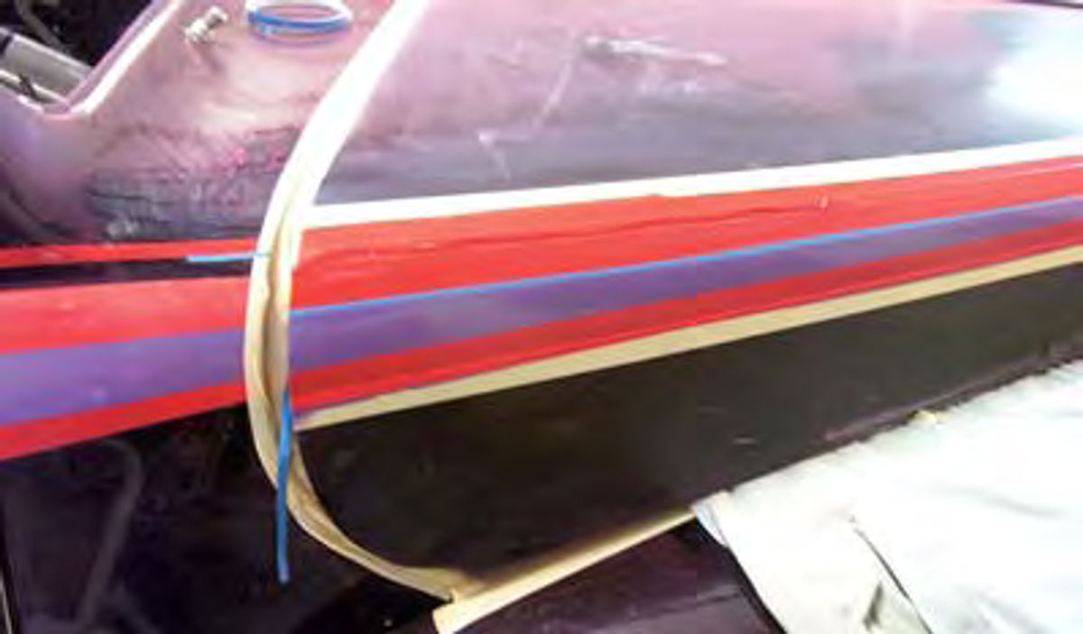
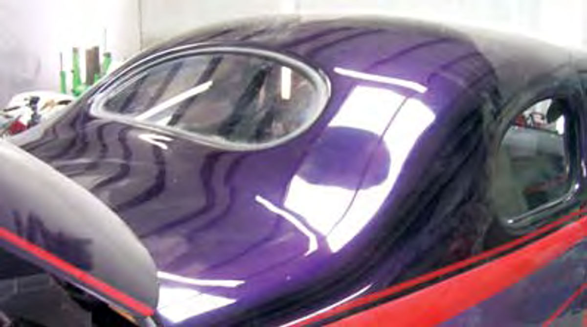
Take a look at Photo 1 and you’ll see that I’ve already painted the fenders. That will let me install the hood and complete the graphics work by laying out the tape lines for the two colors, red and light purple (Photo 2).
The tape lines extend from the cowl down the length of the hood where they will turn down and taper to a point near the front (Photo 3).

Next I masked off the hood and sprayed on the two colors (Photo 4). Notice that I didn’t remove the hood before applying these colors. Base colors don’t tend to over spray like clear coats. Once these colors are dry enough for the hood to be safely handled, in about two hours, I’ll remove the hood and give it three more coats of clear.
Once that is completed, I’ll call the painting portion of this project done.
The Assembly Begins
Assembly begins by adding more insulation. I know I’ve already given this ride some serious insulation using the spray-on Lizard Skin products (February) but this is a completely different type of insulation. This is an insulating material commonly referred to as rebond. It can consist of scraps of cotton cloth bonded together into a thick padding or be made of scrap foam bonded into sheets. The cotton cloth version can be found under the carpet of just about any factory vehicle on the road. The foam version is most often found in hot rods or under the carpet in the bedroom. Either of these products will work great. I elected to go with the foam version because this is what my local trim shop sells and it is very easy to cut and install.
Why add more insulation? Actually I’ll be blanketing the entire cab of this ride with rebond in anticipation of finishing things off with a little trim. It will add to the quiet inside the car.
I had to think about the additional insulation now because I’m ready to install both the wiper motor and the heater unit under the dash. Once these parts are mounted there is no way I’d be able to access the firewall area behind them in order to cover it with rebond. Adding the extra insulation behind these components will have a muting effect on the noise from the wiper mechanisms and the blower motor.
To install the foam insulation I use 3M #8090 Super Trim Adhesive Yellow and coat both the insulation and the firewall, including the underside of the cowl panel. The Super Trim Adhesive is basically a contact adhesive so I allow it to dry to the touch before pressing the insulation into place.
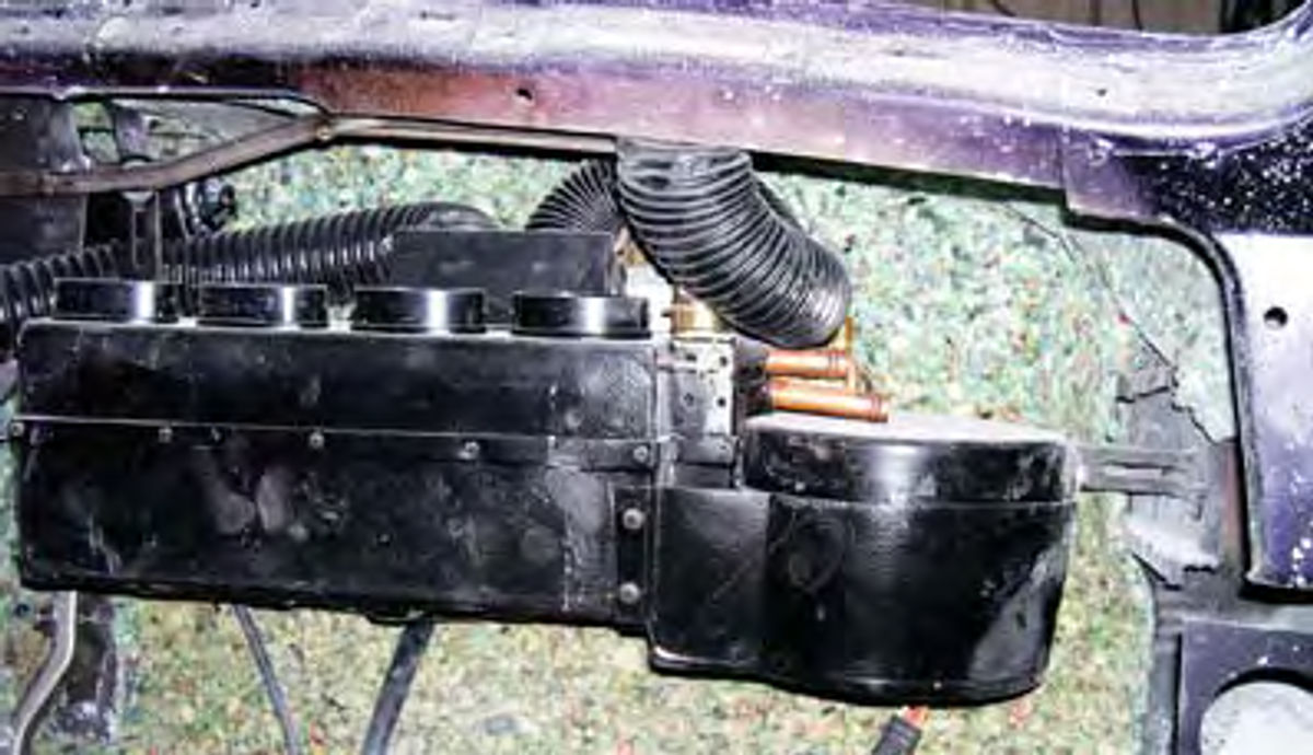
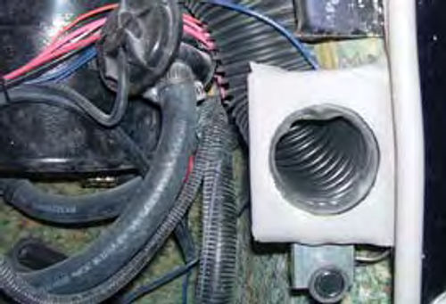
With the insulation in place I can mount the windshield wiper motor and the Hot Rod Air heating and air conditioning unit (Photo 5). I also took the time to route the defroster duct work, the condensation drain hose for the Hot Rod Air unit and the bulkhead plate that transitions the air conditioning hoses from the engine compartment to the interior compartment (Photo 6).

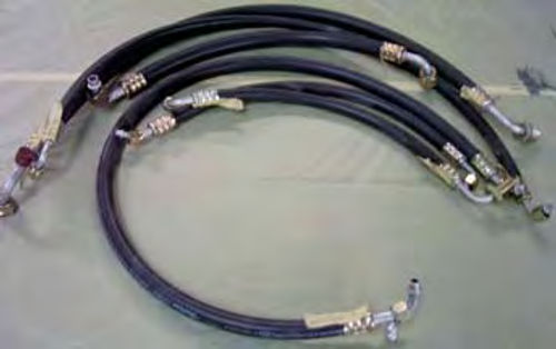
The refrigerant hoses that come with the Hot Rod Air kit are in bulk length and therefore must be cut to fit and the connector ends crimped on (Photo 7). Installing the connector ends is not a do-it-yourself project. Once the system is charged, the hoses will be under a lot of pressure. Getting the connectors professionally installed is a must.
Before I send the hoses out for crimping I’ll temporarily install the connector ends to the unit mounted under the dash, the bulkhead plate, the dryer, the compressor, and the condenser. Then I’ll measure for the hose lengths needed to join all of the components and cut the hoses to length. Once that is done I’ll deliver the hoses, there are six of them, to my local automotive air conditioner specialist and have the connectors crimped to the hoses.

A Tip: Mark the position of the connector ends on each hose before sending them out for crimping. I use a length of masking tape to mark each hose (Photo 8). This ensures the connector is facing the right direction and that the hose does not have to be twisted to make the connection. Twisting can reduce the life of the hose.
Hose installation is a matter of installing the O-rings provided in the kit onto each of the connectors and assembling the pieces. What I won’t do at this time is evacuate the system and add a charge of R134A refrigerant. I’ll save that until I have the car running.
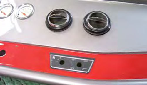
Inside the car I have a couple of cosmetic considerations to think about when it comes to delivering that crisp, cold air to the occupants. First is where to locate the controls. The control panel that comes with the kit is pretty basic and is designed to be mounted underneath the dash. I elected to modify the control panel and incorporate it into the dash (Photo 9). That will make the controls easy to reach and extremely functional. Next I had to think about where to position the duct outlets. The outlets are nice-looking pieces and will look good no matter where I place them.
The only condition to placement is to mount the outlets so that each one, and there are four of them, can be easily directed towards the occupants. Recall that in my chat with the guys at Hot Rod Air I learned the air conditioning works best when the outlets are directed at the car’s occupants.
This is something that I gave some serious thought to earlier in the project. I knew I wanted the face of the dash to be uncluttered so I didn’t want to try and mount all four outlets to that panel. Instead I elected to place two of the outlets near the center of the dash, as seen in Photo 9, and the other two below the dash on each cowl post (Photo 10).
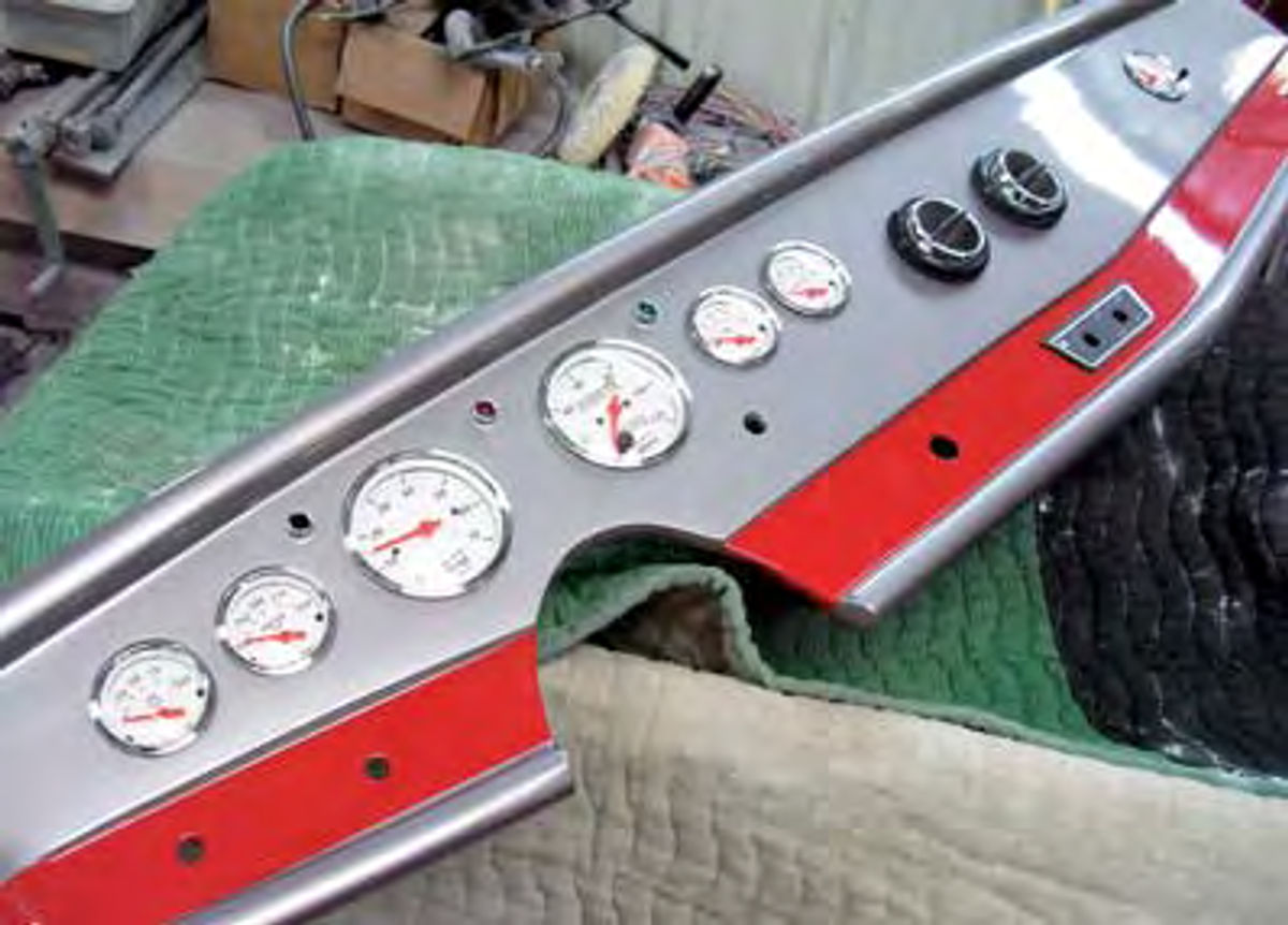
Where did I get the dash? This is a shop-made unit. I used the original dash as a template and constructed this dash out of fiberglass. I gave the new dash a sloping top, in keeping with the shape of the original dash, and a flat front (Photo 11). The flat front gives the dash that clean and uncluttered look I want and it provides an excellent platform for mounting the gauges and switches.
The gauges are from the Auto Meter Street Rod Arctic White series, and consist of a tachometer, speedometer, fuel gauge, oil pressure gauge, temperature gauge, volt gauge and a clock.
A clock? You bet. The clock helps balance the gauges across the dash and since it is made by Auto Meter it matches the other gauges.
The dash is finished in a metallic gray to coordinate with the gray interior colors and is accented by a red band across the bottom. The red band is there to bring the exterior graphics work into the car and will be continued onto the doors in the form of red vinyl trim once I reach that point in the build.
One last detail I had to attend to before mounting the dash panel in the car was to bleed the brakes. The master cylinder is located behind the dash and once the dash panel is installed, bleeding the brakes and adding more brake fluid will be difficult.
To bleed the brakes I start by filling the reservoir with new fluid. Next I attach a hand-held pump-style bleeding device to the right rear brake caliper and pump until the fluid flows through the pump without any air bubbles.
Next I move to the left rear caliper and repeat the bleeding process. I know what you are thinking, one man to pump the pedal, another to bleed the calipers. That’s not necessary with the hand-held pump. This unit allows for one-man brake bleeding.
After that I move to the right front, repeat, then finish with the left front. This sounds easy and it is.
The only thing to remember is to check the fluid level in the reservoir periodically as it only holds so much fluid and must be refilled as necessary. I’ll know the brakes are bled when I have a full pedal that holds solid when I put some weight on it.
The brake pedal feels spongy? There is a leak somewhere in the system. The easiest way to find a leak is to clean the garage floor, press the brake pedal for a minute or so then exit the car and look for the puddle of brake fluid. More than likely you will find the puddle at one of the brake calipers and more than likely the leak is a result of a loose connection.
With the brake work completed the dash can be mounted in the car. Since I used the old dash as a template the new dash uses the same attachment points as the old dash and is easily bolted into place. OK, here’s a good tip. If you have ever tried to wire gauges while laying flat on your back reaching up into the dark recesses of a dash panel, try prewiring the gauges and incorporating a plug-in connector to connect the gauges to the wiring harness. Where do you find a 10to 12-wire connector? Try a GM steering column wiring connector. It will have provisions for up to 15 wires.
Glass Installation
With the top on the ’46 being chopped a full three inches, picking up the phone or dialing up the Internet in search of glass is basically a waste of time. Without a doubt, I can find and purchase new glass to fit a stock 1946 Ford Business Coupe, but ordering glass to fit my three inch chop would be like ordering steak at the local snack-in-a-sack eatery. You’re just not going to like what you get. I have to find someone who can custom-cut new glass to fit this ride.
I did try browsing the Internet and found several sources that can cut laminated glass to fit just about anything. The problem is that they relied on my ability to measure and correctly template the glass openings so that the glass could be cut to the correct sizes. In some worlds that may be great, but in my world things often go wrong and when they do I usually find myself back at square one wondering what happened. It’s the wondering where things went wrong part of that scenario that prompted me to call my local glass guy and have him come by the shop. Recall that earlier I had talked to my glass guy and placed my name on his job list. He’d been waiting for my call and was ready to help me out.
Remember the saying about good cooks? “When the chef turns on the stove, your job is to sit in the corner and peel the potatoes.” Good glass guys are the same way. They’d rather you go somewhere else and peel potatoes while they work. It results in far less glass breakage.
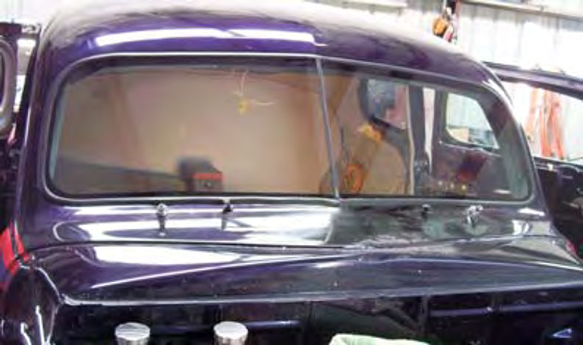
Starting at the rear of the car, the back glass is completely stock and only needs a new rubber gasket to hold it in place. Steele Rubber provided me with an exact factory duplicate gasket. Since this was a stock-sized replacement, it came as clear glass. In order to get it to match the side windows, which will be cut from dark tinted glass, my glass guy took the time to apply a tinting film to darken it before installation (Photo 12).
As mentioned above, the side glasses for the ’46 are tinted, and were cut from laminated sheet glass. The actual method used to cut the glass is something of a secret but as I understand it the process is similar to the sandblasting method used to engrave stone. But what do I know? Since the quarter glasses are stationary, the installers set this glass in urethane. They aren’t coming out, ever. The door glasses are urethane-set in the power window run channels.
The windshield consists of two pieces of flat, laminated glass cut and beveled so that the pieces can be butt-joined in the middle. I’ve seen a number of hot rods with no center-mounted vertical bar between the two pieces of glass. It’s a good look, but the seal between the two pieces of glass is made using clear silicone. That works great for a while, but sooner or later the silicone will break down and have to be replaced.
To avoid this problem I used a narrow black plastic strip as a vertical bar. It has a very clean look to it and since I can urethane it into place it will be there forever, with no digging it out to replace it.

As for installation, the technicians wrapped a one-half-inch wide black plastic beading around each windshield glass and then urethane-set the glasses into place, one at a time (Photo 13).
The center bar, which is a 3/8-inch wide strip of black plastic, is urethane glued between the two glasses only after the glasses are in place. How does the new windshield look? Not bad. The plastic beading may be there to help hold the windshield halves in place, but it really gives the installation a very professional look (Photo 14).


