
Installing the Wiring and Steering Systems
Although I still have paint work to do on this ride, such as refinishing the hood and front fenders, I’m going to suspend the painting process for a little while and take care of some other aspects of this build. Once that is done, I’ll paint the front sheet metal pieces and install them.
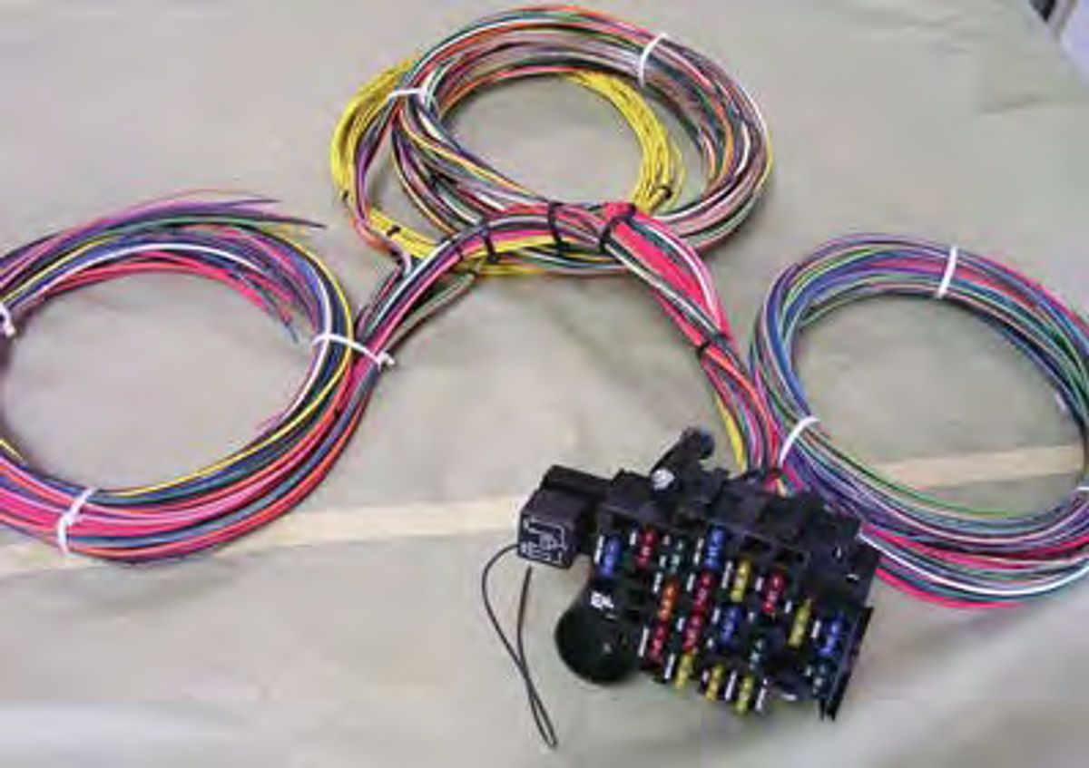
I’m taking this approach because I don’t like the thought of leaning over freshly painted fenders to complete the necessary wiring, engine and steering work that needs to be done to this car before I can turn the key and take the ’46 for a spin. So I’ll start with the wiring and bring out the Painless Performance Products wiring kit ordered previously (Photo 1).
The heart of the electrical system is an 18-circuit harness designed to accommodate all of the power accessories planned for this car and then some. This harness is also available in a 12-circuit version for cars with fewer accessories, but, as you may already know, project cars are always in flux. Extra circuits can often be a real gift when adding goodies to the ride.
If you read the fine print on the harnesses available from Painless, you will find two types of universal harnesses. One is configured for a column-mounted ignition switch and the other is for a dash mounted ignition switch. The harness I ordered is for a dash-mounted switch.
I can’t take you through the entire installation procedure wire by wire so
what I’m going to do is offer a number of tips and methods I used to wire this car. To start, Painless Performance has been at this for a number of years so you can trust that when you purchase one of their products, it is going to work. If you do have a problem with one of their kits, more than likely the guys at Painless have already found a cure for it. Go to their Web site or call their tech line. You won’t be stuck on hold for hours on end, and they can help you fix just about anything that can go wrong with the installation of one of their electrical systems. When you open the 18-circuit harness box the first thing to look for is the Wire Harness Installation Instructions. On page 1 you will find the wiring group headings—Engine/Headlight Group, Dash Group and Rear Light Group. Read each group section thoroughly to familiarize yourself with the product before you do anything else.
After reading all three parts of the installation instructions, lay out the new harness and separate it into the three sections (Photo 2). You’ll notice in the photo that all three sections key off of the fuse block. That means that every circuit in this harness is fused to protect the system should a short occur.
The next step is to determine the best way to route each group of wires in the car and to establish a plan for wiring each individual electrical component in the car. This is basically roughing out the wiring, and if there is one thing to keep in mind, it has to be that each group of wires must be routed in an area where possible damage to the wiring can be avoided.
That means if the wires must be routed under the carpet, you should place them next to the console or out near the scuff plates, not in the open where foot traffic or seat tracks might eventually degrade the wires and create a short circuit.
I elected to route the Rear Light Group through the center console, then I divided the group so that the wires operating the electrical components on the right side of the car were routed over to the right quarter panel and the wires operating the electrical components on the left side of the car were routed over to the left quarter panel. From the quarter panels I can route wires into each door (suicide opening), up to the roof panel for a dome light, and toward the rear of the car for the taillights.
The Dash Group is self-explanatory as to where these wires belong. Incorporated in the Dash Group are the fuse panel, gauge wiring, wiper circuit, headlamp switch circuit and steering column circuit. The steering column circuit includes components such as the turn signals, emergency flashers, headlight dimmer switch (on some columns) and horn button.
Breaking the components of the Dash Group down further, I mounted the fuse panel on the firewall just to the left of the steering column. For the time being I’ll leave the gauge wiring circuit stuffed into the area above the steering column so that once I’m ready to install the dash gauges, the wiring will be ready for mounting.
The remaining Dash Group circuits, such as the headlight switch, wiper switch and steering column wiring, will be routed to their proposed locations and left there until later.
The Engine/Headlight Group
This is the meat of the wiring harness as it controls the headlights, parking lamps, front turn signal lamps, electric cooling fan, electric fuel pump and everything else engine related. This part of the harness also contains the firewall pass-through bulkhead plug that allows the harness to transition from the dash area to the engine compartment. Painless provides a template, found at the back of the instruction manual, to use for cutting this opening.
Breaking an 18-circuit harness down into individual circuits and then wiring each one can be a daunting task, especially if this is your first rodeo at wiring a car. To help with that, Painless provides detailed instructions throughout the manual as well as a variety of basic schematics to help lead you through the process.
The schematics are found near the back of the manual and provide specific information on each circuit, including things like the number and color for each wire required for that circuit.
If, after reading the manual and checking out the schematics, you still aren’t sure where a particular wire goes, refer to the chart at the very back of the manual. An example is wire #901. This wire is gray with a white tracer stripe, is 18 gauge, and starts at the engine cooling fan switch and goes to the fan relay. If you have your glasses on, you can even read the words “Fan Relay” printed on the wire.
Every wire in the harness is color coded, numbered and named in the same manner. That makes finding a specific wire a simple matter of checking the color, reading the number, then identifying the wire by name. It beats the heck out of crawling through the car trying to follow a wire back to its source.
If you like to test your work as you go along, I suggest starting with the charging circuit. This is part of the Engine/Headlight Group and will include wiring for parts such as the battery, starter and alternator. This will let you begin to power up the car using a battery charger as the voltage source. Forget about using
the battery as the voltage source. It cranks out too many amps and could easily fry a few wires should you hook something up wrong. Once the charging circuit is up and running, it is a simple matter of moving through each remaining circuit until the car is completely wired.
Tools You’ll Need
• Crimping Tool: Use a quality crimping tool to avoid over-crimping the terminals. • Wire Stripper: This is often a two-inone with the crimping tool.
• Test Light: I use both a test light and a multi-meter. The test light tells you if the circuit has power. A multi-meter will tell you if the circuit is receiving the correct voltage or if the circuit has continuity via the ohm feature of the meter.
• Hole Saw: I use a hole saw kit purchased from the local home improvement center. The kit contains various hole saw sizes and must be capable of cutting thin metal.
•Battery Charger: This is a very important tool as it is used to provide voltage for testing various circuits. A 10 amp or less charger is recommended.
• Heat Shrink Tubing: Purchase this product at the local home improvement center and use it to cover and protect every terminal in all circuits. Not only does this decrease the chances of grounding problems later on, it also gives your work a more professional appearance.
The Fuel Injection System
Early into this project I made the decision to toss the carburetor and go with a more up-to-date fuel management system. With gasoline surpassing $3 per gallon, the decision just made good sense.
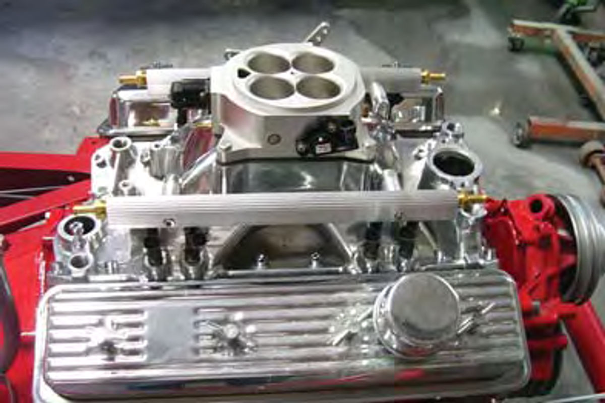
I opted for an Affordable Fuel Injection system (Photo 3). This is a TBI (Throttle Body Injection) unit, and one of my thoughts when selecting this particular unit was that I wanted a great-looking unit that could be installed without a hitch and that at a quick glance could pass for a carburetor sitting atop the engine. Once I install a chrome air breather on top of this unit, it will be hard to tell this is not a carburetor.
The best thing about selecting a unit from Affordable is that the unit is set up specifically for the engine being used. What does that mean? I gave the engine specifications, camshaft specifications and desired performance specifications to the guys at Affordable, and they built and calibrated the unit to fit my car. I don’t need a laptop with graphs I can’t decipher or a travel agent to entice someone into coming to the shop just to make my car run. All I need to do is follow the easy to-read instructions and all will be well.
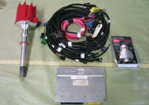
Of course, there are other considerations to work out when installing a fuel injection unit. Take a look at Photo 4. These are some of the other components that come with the kit and they include an ECM (Electronic Control Module), distributor, wiring harness, fuel pump, fuel pump regulator and various sensors.
Some of these remaining components, such as the distributor, wiring harness, and sensors, can be installed on the
engine now. The ECM box will need to be mounted somewhere under the dash, and we’ll need to drill a hole through the firewall to route the wiring harness from the engine to the ECM. These are considerations that I will have to delay until I have more of the dash assembled. I can’t afford to drill any holes in the firewall that might interfere with the mounting of something else. Nor can I mount the ECM until I know where it will fit best. I’m thinking that behind the old glove box location and just above the heater box will be the ideal spot.
Installation always starts with reading the instruction manual. Once you’ve read it, you’ll wonder why you ever tolerated a carburetor. The manual is thorough and every component is connector coded so you can’t mess things up. It only took me a couple of hours to make the installation, and all I’ll have to do later is provide a 12-volt source to the ECM and to the fuel pump.
Steering the Car
I have a steering column and the rackand-pinion unit, but at this point there’s no way to connect the two. For that I’ll need a steel steering shaft, and it will have to snake its way through the firewall, down past the left-hand exhaust pipe and alongside the frame rail. This is by no means a straight line so it will be necessary to add at least two universal joint-type couplers to get the shaft to bend where necessary.
I don’t want either of the bends to be sharp bends. Sharp bends can affect the way the car steers by creating stress points at the universal joint couplers. These stress points are best recognized as hard spots in an otherwise free-turning steering wheel. To prevent this kind of problem, I want to make certain my bends are 30 degrees or less.
It won’t present a problem with this unit, but occasionally it is necessary to add more than two universal joint couplers to join the steering column to the rack-and-pinion unit. When that becomes necessary, a pillow block, or bearing-mounted support bracket, must be added to the shaft assembly to ensure that the assembly is completely stable. Three universal joint couplers can cause the steering shaft to wobble when turned. That’s not acceptable.
To make up the shaft extending from the steering column down to the rackand-pinion unit, I start with two 24-inchlong, 3/4-inch diameter DD shafts and cut one stick 12 inches long and the other 14 inches long. What is a DD shaft and where do you purchase this product? The DD stands for “Double D” and that describes the cross-sectional shape of the shaft. This is a very common steel steering shaft used to make up steering links between the steering wheel and the steering gear box or rack-and-pinion unit. I found several sources for both the shaft and the universal joints on eBay.
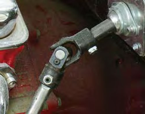
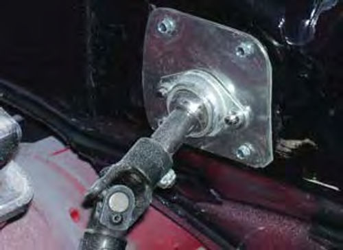
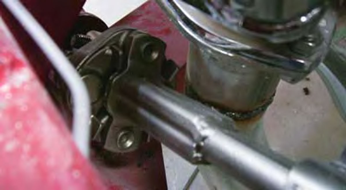
To make the bends in the shaft, I use universal joints designed specifically for this purpose (Photo 5). One other piece I need to add to ensure that the shaft remains stable is a bearing block bolted to the firewall where the shaft exits (Photo 6). This is not the same animal as the pillow block bearing support mentioned earlier as it isn’t there to prevent the shaft from wobbling when turned. Its function is to help support the steering column as well as help keep the steering shaft centered within the column.
Finally, I’ll add a vibration dampening coupling at the rack-and-pinion (Photo 7). This coupling separates the shaft from the rack-and-pinion to prevent road vibration from telegraphing up through the shaft to the steering wheel.
The last thing I can do with the steering is center the steering wheel. This is by no means a way to align the front suspension, rather what I am doing is verifying that the suspension work already performed has been done correctly and that when I deliver the ’46 to the front end alignment shop for an alignment all will go well.
This required raising the front of the car with a floor jack and moving the jack stands to a point under the frame just behind the front wheels. I need the spindles to move freely.
Now I turn the steering wheel full right. With the wheel turned full right, I turn the wheel left, counting the revolutions until the steering wheel stops. That’s two and a half turns, divided in half equals one and three-quarters turns. Now I turn the steering wheel back one and three quarters turns to center it.
Looking at the front brake rotor discs, they should be pointed straight ahead. If not, I use the tie rod end adjustments at the rack-and-pinion to adjust each spindle, one at a time, until the rotors are pointed straight ahead. I tighten the adjustment nuts to secure the tie rods. The steering wheel is centered as best as can be without the aide of a pro.
The last concern here is to be sure the turn signal switch in the steering column operates correctly. To do that I flip the switch lever down, turn the steering wheel to the left a half turn, then return the wheel to center. The switch lever should click and return to the “off” position. I repeat this procedure to the right. The switch lever should click and return to the “off” position.
Next on the list is the power steering pump. I elected to use a Saginaw brand pump. This pump was standard equipment on GM products for many years and will work quite well with my rack-andpinion unit. The only catch here is coupling the Ford rack-and-pinion unit to the GM steering pump. To accomplish this marriage, I began with a visit to my favorite automotive reclamation center in search of mounting brackets for the pump. While there, I also scavenged the high pressure line from a salvage Saginaw pump.
I also visited the Ford section of the reclamation center and scavenged both the high and low pressure lines from the rack-and-pinion unit on an ’82 Thunderbird. Am I about to install worn-out power steering fluid lines on the ’46? No, I’m not. I just want to be sure these are the correct-size lines and that they will screw into my rack-and-pinion unit and my power steering unit.
When I know the lines fit, by screwing the lines into my rack-and-pinion, I’ll take them to my local hydraulic line manufacturer and have them construct new lines to fit my married components.
How about installing a used power steering pump?
No. Remanufactured units are available at most automotive parts stores, and, if desired, chrome plated pumps are available from several hot rod parts providers.


