
How -to Rebuild a Vintage Heater
He Wanted This 1948 Unit to Work With a Modern Engine. That Required a Redesign & a New Core and Motor.
OVER MY EXTENDED career as a car nut I’ve had the occasion to restore a wide variety of vehicles and vehicle components. Well, not long ago a customer brought in the remains of an original heater from a 1948 Ford and asked if there was any way I could restore it and update it to 12 volts. Since I had already mouthed off and claimed to be capable of restoring or updating just about anything automotive, I knew I had no choice but to do something with it. So, I tossed the heater onto the bench and gave myself a few days to think about what could be done.
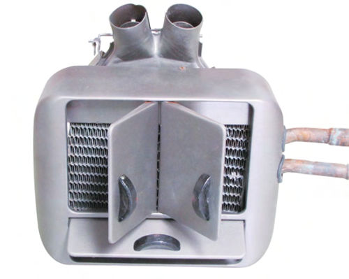
Here is the heater in question (Photo 1). From the outside it looks to be in pretty good condition. There is no visible rust, which is a paramount issue when working on one of these units. All of these units were made of steel and all of them contained the heater core, which was prone to developing leaks. Any rust on the outside would translate into lots of rust on the inside. And that translates into an unusable chunk of metal.
While you are checking it out, be sure to notice that this unit has two round outlets located at the top. This might be what was known as the deluxe model asthese outlets are for the windshield defroster vents, one on the right side, and the other on the left. If you look really close you can just make out the remains of the cable end that was used to control the two flapper doors located inside the outlets. The flappers either closed or opened these vents depending upon the need to defrost the windshield.
The three doors on the front of the unit act to direct the warm air where it’s needed, either to the right, the left, straight down or a combination of any of the above.
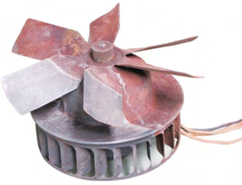
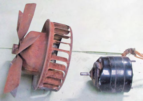
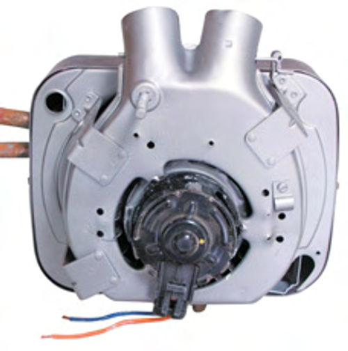
The business end of this unit consists of a heater core and a 6- volt fan motor that has both a blade-type fan and a squirrel cage fan attached to it (Photo 2). Why the dual-purpose fan? The blade part of the fan pushes air through the heater core where that air is warmed and then directed out through the three doors shown in Photo 1. The squirrel cage fan directs air to the round defroster vents located on top of the unit. If you study this configuration for a moment it becomes obvious that the air reaching the windshield does not go through the heater core. That makes sense as you don’t want overly warm air hitting a cold windshield. Extreme temperature changes have a way of equating with cracked glass.
The heater core itself doesn’t need much explanation. It worked just like heater cores do today. It took warm water from the engine and converted that energy into heated air.
Formulating a Project Plan
The goal here isn’t so much to get this antique heater to produce more warm air, the goal is to first get it to work; then,second, get it to work with a 12-volt system.
That means replacing the old, leaky heater core with something that can be adapted to work with whatever engine and firewall changes the owner decides to make, if any. This also means changing to a heater core that—should replacement ever become necessary— that replacement can be purchased over-the-counter at the local O’Reilly’s Automotive Parts store.
On my end it also means I end up spending a lot less money for the core. I spent a couple of hours looking for an exact replacement heater core before making this decision. The estimated cost for the replacement came in around $120 plus shipping. That’s hard to justify when I can make a few changes and install a newer model core for less than $30.
Asforthe motor, the plan calls for giving the old 6-volt motor the toss and replacing it with a modern 12-volt motor. That may sound like a tough task considering the mounting differences, but as you will see the process proved to be much easier than I thought it would be.
The Restoration Process
This restoration starts with disassembly. The unit has four screws holding the case halves together and a couple of bolts holding the motor in place. It doesn’t take much to break it down into the individual components.
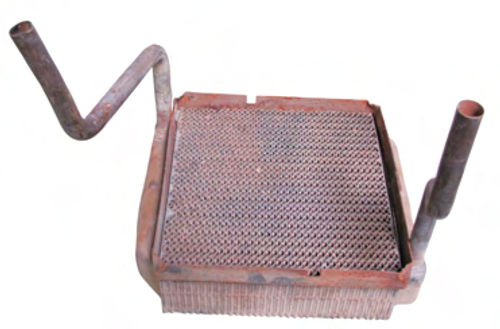
The next step is to measure the old heater core. This particular one measures 10 x 8 inches and is 2 1 ⁄2 inches thick. You should also notice, (Photo 3), that the old core has exceptionally long inlet and outlet tubes, thus the reason for the high cost for an exact replacement. These long tubes would have exited through the fire wall at about the same height as the water pump on the original engine.
Since this car is going through some extensive modifications, one of which calls for an engine swap to a V-8, having the heater core tubes extending through the middle of the firewall is not going to work. That’s a good thing since that allows me to look for a new heater core with the approximate dimensions of the old one and not have to worry about the length of the tubes.
Note: The vehicle owner has expressed a desire to locate the heater higher on the firewall, thereby shifting its location from the floor pan to a point just beneath the dash.
My thought is that the heater can be mounted facing the passenger side or even mounted so that it is facing down. Either way allows for the heater hoses to be routed up the right kick panel then across and behind the dash. That puts the hot heater hoses in locations that can’t be easily accessed, which reduces the chances of someone accidentally touching one of them and being burned.
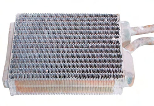
The heater core I selected is a Ford unit, O’Reilly’s #398010, and will set you back about $20. The dimensions of this unit are 9 1 ⁄2 x 6 x 2 inches (Photo 4). The size is typical for heater cores used today so when it comes to finding the right core, the trick is to find one with the inlet and outlet tubes pointed straight out to the side. This configuration works because the tubes can be routed straight out the sideofthe caseviaholesthatI’ll drilllater.
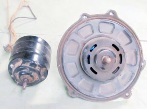
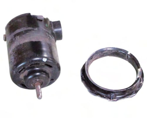
The blower motor is also a Ford unit, O’Reilly’s #PM251, and will set you back about $30. The issue here is how to get this motor to mount where the old motor was located. Check out Photo 5 and you can see there is a huge difference between the two motors. How in the world is this ever going to work?
I started by removing the fan from the 6-volt motor (Photo 6). The fan is held on the motor shaft by a set screw. Remove the screw and the fan will slip off of the shaft. Something that you can’t see when looking at any of the photos is that the shaft on the 6-volt motor measures 5/16- inch in diameter while the shaft on the 12-volt motor measures 3/8-inch in diameter. That isn’t an issue since the fan can be mounted in a drill press and drilled out to 3/8-inch to accommodate the larger-sized shaft. Once the set screw is installed it will tighten against the larger shaft and hold the fan in place.
Getting the New Motor To Fit
The real issue is how to mount the new motor in the case. After a little head scratching the answer became apparent. I trimmed the large, flat mounting plate on the new motor until only a half-inch of flange remained. I then heated the reduced flange using a heat gun until the adhesive holding the flange to the motor softened. I then slid the flange off of the motor (Photo 7).
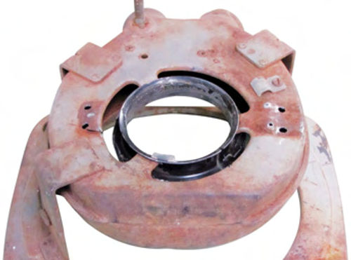
The next step was to cut away a portion of the rear case so that the flange could be welded to it (Photo 8). The trick here is to perfectly center the flange in the opening. How do you do that? The flange piece is centered on top of the case half by taking some very careful measurements and marking everything before doing any cutting.
Next, I slid the motor back into the flange then mounted the fan to the motor. The entire assembly is set into the case half to check for clearance around the fan. Once the clearance was right on the front of the rear case half, that is, the fan wasn’t touching the case at any point, I tack welded the flange in place. No solid welding until the motor is removed. Welding can cause arcing across the bearings inside the motor and if that happens, the motor is ruined.
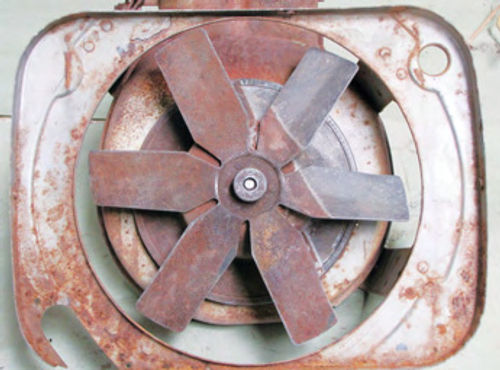
You can see here just how critical it is to get the right fit (Photo 9). If the motor isn’t perfectly centered in the case, the squirrel cage portion of the fan will scrape the sides of the case.
The flange is then securely welded to the case half. After that the motor goes back in, itslidesin from the outside, and the fan gets reinstalled for a final test fit.
Doing a final test fit doesn’t mean attaching the fan and spinning it. It means attaching the fan and powering it up. If it operates silently then all is well. If not, the fan can be moved either up or down on the motor shaft or the motor itself can be tweaked to one side or the other to provide more clearance.
Fitting the Heater Core
Switching gears and moving to the front of the case, half the big thing here is to test fit the replacement heater core (Photo 10). Notice in the photo that I’ve attached the rear case half while the motor and fan are still attached. I need to be sure there is adequate clearance between the fan blades and the heater core. That clearance needs to be at least a half-inch.
Also notice that I drilled two holes in the side of the front case half to allow the inlet and outlet tubes to protrude. The holes are 1-inch in diameter. What you don’t see in the photo are the two rubber grommets I’ll install in the holes after the heater has been painted.
Now pay particular attention to the air gap above the heater core. This is the price for making the swap to a newer-style heater core. The core size shrunk, drastically.
What I can’t do is leave the gap. All of the air from the fan would take the path of least resistance and the heater would not produce much warm air. The cure is to weld a baffle inside the case half to fill this gap. You can see the baffle in Photo 11, a front shot of the completed unit.
The last step is to use foam insulation strips, find this foam on the door and window insulation aisle of your local home improvement center, and use it to fill the voids around the heater core so that you end up with a heater core tucked snugly inside the case half.
Once everything is as it should be— the entire unit has been assembled and the fan motor powered up and run for a minute or two without binding anywhere—the unit is then disassembled and the fan and motor removed so that the case halves and the fan can be media blasted prior to painting. What media will I use? In this case I opted for coal slag because it will remove the surface rust on the fan blades.
Next the unit gets a coat of paint. This unit is going inside a car with a gray interior so I opted for a gray single-stage urethane finish. I painted the heater inside and out (Photo 12).

Mounting Plan Still To Be Determined
Originally this unit bolted directly to the firewall using three long bolts that extended from the rear of the back case half and went through holes drilled in the firewall. To make the necessary modifications for converting this heater, I had to remove those bolts. Once the car is back in the shop I’ll make a decision as to how this unit should be mounted and only then will I fabricate the new mounts.
Electrically Speaking
As you may already know, most heater blower motors have a power wire and a ground wire. What that means is that the low and high speeds for the motor are controlled through the use of a resistor. Many GM products produced in the ’70s and ’80s used resistors that were mounted in the heater/air conditioner case located inside the engine compartment. A two- or three-position switch was connected to that resistor to vary the voltage being supplied to the motor. This is one way to get a variable-speed heater motor. Another is to use a switch that has the resistor incorporated into the back of the switch. Some older model Corvettes(1970) used this type of heater switch as did a number of vintage vehicles from the ’50s and ’60s. If you want something retro-looking, I Suggest darkening the door to your local parts store. Your parts guy will have at least one catalog dedicated to electrical switches.
But no matter how you elect to power the motor, be sure to fuse the power wire going to the switch. I suggest adding an inline fuse with a 15-amp fuse.
More and More Heat
Then there is the issue of constant heat if you don’t add a cutoff valve somewhere ahead of the heater core inlet. This valve can be placed anywhere that’s convenient, and in the absence of a vacuum control mounted on the dash to turn this valve on or off you can simply open it during the winter and close it during the summer months.
I found a vacuum-controlled cutoff valve at O’Reilly’s #YG–136. This valve can be manually operated by removing the vacuum controller.
Got a question? Send it along.
Resource
O’Reilly Auto Parts


