
How -to Basket Bird Revival
It Arrived At His Shop Seeming Like It Was Headed for Salvage. Now This ’55 T-bird Has a Showroom-New Look Again.
REMEMBER THE BASKET BIRD? I First gave you a look at this 1955 Thunderbird back in the August 2006 issue. The car truly was a basket case but since the VIN indicated it to be one of first Thunderbirds built, I knew the car had to be restored. That task took quite a lot of time and since it took me so long I’ll give you a quick review of what I did to the car previously then bring you up to date on its completion.
A Tale of Two Primers
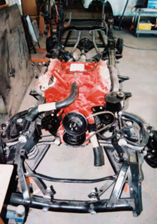
The Basket Bird arrived at the shop on a trailer and in pretty sad condition (Photo 1). Some work had already been done to the car, but that work was very suspect and my only option at that point was to start over. That meant removing the body so that it could be stripped clean then completely restoring the frame, suspension, and drive train components (Photo 2).
After that I did an enormous amount of rust and dent repair to the body.
How enormous? I showed you Photo 3 in the first installment, but this repair is so far from acceptable I deemed it appropriate to show it again. This is the left fender at the door opening just below the windshield post. I can’t tell for sure, but this patch may be an old license plate, complete with embossed lettering. This type of repair had to be removed and reworked. No ifs, ands or buts.
All of this brings me to where I ended the first article, with an application of two coats of PPG DP74LF epoxy (red) to the underside of the body and two coats of PPG DP70LF epoxy (gray) over everything else.
Why the two different colors of epoxy? I found red oxide primer under the original paint on the underside of the car so going back with a red-colored epoxy in that area was a must.
However, when I removed what was left of the original paint on the core support structure behind the grille, and from inside the trunk area, I found gray primer on those panels.
That told me that for whatever reason Ford decided not to apply the red oxide primer to the entire car and since my goal was to put the car back as close to original as possible, I went with the two colors of epoxy for my initial coats.
Adding Some Tint to the Base Color
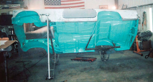
That brought me to the point where I could refinish the underside of the car and the engine compartment starting with a coat of PPG Global D8072 sealer, three coats of PPG Global base #12827- tinted, and three coats of PPG Concept DCU2002 polyurethane clear (Photo 4).
What’s the deal with tinting the PPG Global base color? If you are familiar with the original turquoise blue Ford used to paint these cars you know this is an extremely washed-out color. The owner of the car wanted to stay within the parameters of the original color but preferred that the color be a little stronger, which basically meant the turquoise needed more blue. To accomplish that goal I asked my paint supplier to mix two samples of the color and adjust the amount of blue in each one until we came up with an acceptable tint.
I don’t want to get into a color tinting tutorial here, but you can alter the shade of any color by adjusting the grams of the primary colors used to formulate the final color. In other words, to make the first of the two 8 oz. samples we reduced the amount of white used in the original turquoise blue formula by a few grams and increased the amount of blue used in the formula by the same number of grams. To make the second sample we reduced the amount of white even more and increased the blue by the same amount.
Knowing exactly how many grams of color that were added and subtracted to make up the 8 oz. samples made it easy to make the same color ratio adjustments when we mixed the full gallon of paint it took to spray this car.
Why Mix 8 oz.samples? Having Mixed a lot of paint over the years I’ve found that mixing samples smaller than 8 oz. can result in inconsistent colors.
Keeping the Overspray Away, Adding a Coat of Filler & Being “Frame Neutral”
With the underside of the car refinished, the next step is to set the body back down on the frame. Notice in Photo 5 that I have the car supported on four jack stands. The two jack stands up front are stationed out at the lower ball joints and the two at the rear are stationed under the rear axle.

I’m going to talk about why this is important in a moment, but first there are other details visible in the photo that you need to know about. For starters, notice the masking tape covering all of the openings on the firewall (visible inside the passenger compartment). Masking these holes keeps engine compartment paint from entering the passenger compartment. I previously spent a lot of time sanding and prepping the passenger compartment and trunk area for paint so the last thing I wanted was to get engine compartment overspray in those areas. A little masking tape works wonders when it comes to protecting those areas. Yes, all of this masking tape goes away and is reapplied on the opposite side of the openings before spraying the interior compartment and trunk area. It is a very easy way to prevent overspray from reaching areas I’ve already painted.
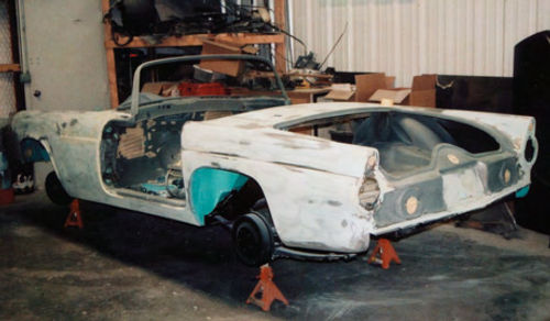
Next, notice that I Smoothed the exterior of the car using a lot of plastic body filler. It is impossible to tell, so take my word that what you are seeing is actually a very thin coat of filler. That coat just happens to extend from front to back and everywhere in between. How long did it take to smooth this body? I spent about three weeks getting this body ready for primer.
This also is the point in the process where the headlight housings, tail light housings, and the doors get mounted to ensure a good fit. The headlight housings are made of pewter and are painted the same color as the car. That means they must fit in perfect alignment with the fenders. Being made of pewter also means they easily can be broken should I try to reshape them. That, in turn, means all shaping and tweaking had to be done to the fenders, not the housings, thus the reason for fitting these housings now.
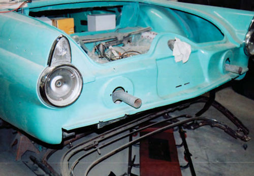
At the other end of the car the tail light housings are chromed and they are made slightly smaller than the openings where they mount (Photo 6). This is a finished shot, but you can see these units need an exposed 1/8-inch “halo” of painted surface around the edges. Perfection with the halo meant spending a lot of time getting the quarter panels shaped right. The doors are a whole other issue and are the primary reasons I placed the jack stands under the suspension components. Also known as placing the stands “frame neutral,” what this positioning does for me is to ensure that the frame had zero stress placed on it. If I put wheels and tires on the car right now this is exactly how the car would sit. This is especially important because this car is a convertible and that makes the fit of the doors dependent upon the fit of the body to the frame.
What if I placed the jack stands under the frame rails instead? This Frame has a little bit of twist in it. That’s nothing to be alarmed about as most frames eventually end up with a little twist, particularly if the vehicle happens to be a convertible.
Frame twist occurs naturally because of engine torque and roads that are anything but flat and smooth. Twist is more prevalent in convertibles because the body lacks the structural strength found in cars with a roof. Finding a little twist in this frame wasn’t unexpected but I did need to keep that fact in mind once the body was back on the frame.
How much frame twist is acceptable before the frame needs to be hauled off to a frame shop for repairs? I don’t like to see more than a half-inch of twist from end to end with the frame sitting on jack stands and the measurements taken from each corner of the frame down to the shop floor. If you find any more twist than that I would suggest darkening the door to a good frame shop for an estimate on repairs.
Getting back to the jack stand placement, had I positioned the stands under the frame rails, mounted and aligned the doors, then sat the car on its wheels, chances are the doors would no longer fit because of that little bit of twist I found in the frame while I had it mounted on the jack stands. That’s a mouthful and hopefully a good explanation as to why when given the option you should always place jack stands under the sus- pension and not under the frame rails.
Time to Hang Those Doors
Hanging the doors actually started with the installation of the body mount bolts. Having those bolts in place tells me that the body is correctly aligned to the frame. While under the car starting the nuts on all of the bolts I took the time to check for gaps between the body and the frame at the right and left body mounts located directly under the cowl. The right side was flush; the left had a 1/8-inch gap, a result of that slight twist in the frame I mentioned earlier.
I added one 1/8-inch body shim to fill the gap. I had plenty of shims on hand as I removed several from the body mount locations during tear down. Finally, I snug tightened those two bolts. What’s important here is to note that I’m only working with these two body mount bolts, all of the rest of them are left loose for now.
What size are the shims I’m using? They are all “U” shaped, measure about two inches square, and are 1/8-inch thick. All of them are original Ford shims that I removed from the car previously then media blasted clean and coated with Eastwood Zinc Phosphate #10281Z.
Next I mounted both doors on the car and aligned them to the fenders. My only concern here is to maintain a 3/16-inch gap between the forward edge of the doors and the rear edge of the fenders, making sure the doors are flush and even with the fenders, and getting the body line that runs along the sides of the car perfectly even.
That let me begin the real work of aligning the doors to the body. In case you are wondering, both doors are empty shells, no latches or glass. With the doors aligned to the front fenders the next areas of concern are the rocker panels. I want that same 3/16-inch gap between the bottom edge of the doors and the door opening at the rocker panels.
Let’s assume a wide gap exists at the rear of the door on the left side and the gap on the right side narrowed toward the rear of the door. To close the wide gapontheleftsideIneedtolifttherear of the body on the left side and insert a 1/8-inch shim under the body mount bolt locatedjustforwardoftheleftrearwheel house opening (at the rear of the door). That bolt is then snug tightened and the rocker panel gap checked. That gap should close. If more shims are needed to close the gap they can be added.
On the right side I have the opposite problem; the door-to-rocker panel gap is narrowing down to about 1/8-inch toward the rear of the door. The first thing I want to do is snug tighten the body mount bolt just forward of the right wheel house (at the rear of the door). If that doesn’t pull the body down and open the gap I need to go back to the mount at the cowl, lift the front of the body, and add a shim to that mount. That will lift the front of the door and also widen the gap at the rocker panel.
The final adjustment for the doors is the gap along the rear edge where the doors meet the quarter panels. Let’s assume the gap at the left door is wide at the top of the door. To close that gap I need to add shims to both of the body mount bolts located in the trunk area.
Now let’s assume the gap at the right door is narrow at the top rear of the door. To widen this gap I tighten all of the body mount bolts on the right side of the car. If that doesn’t widen the gap sufficiently the only other option is to loosen all of the bolts on the right side and add one more shim to the cowl mount bolt and one shim at the mount forward of the rear wheel house followed by tightening all of the bolts on the right side.
That leaves me with the core support mounting bolt on the left side. If a gap is present a shim is added, otherwise that bolt and all of the remaining bolts on the left side can be tightened.
That’s a lot of tightening and checking to go through, especially if you toss into the mix having to make small adjustments at the door hinges while all of this is going on, but this is the best way to ensure the doors fit the way they are supposed to fit, which brings me to the ugly news: The doors must now be removed for painting.
I also should add that this is the point in the build where I installed the hood and deck lid to be sure those panels fit and aligned to the body.
Installation included mounting the hinges and latch assemblies. I need to be able to latch both panels so that I can check the hood alignment along the sides of the fenders and the deck lid alignment along the length of the quarter panels. Both the hood and the deck lid have sloping curves along each side. The slightest variation in those areas will magnify greatly once the car is painted so getting these panels perfectly aligned to the adjacent panels is essential.

Refinishing the Car
Aside from repeating that I sprayed this car with PPG Global base coat/clear coat products I can tell you that I sprayed the passenger compartment and trunk area first, then masked those areas, plus the engine compartment and the underside of the car, before spraying the body’s exterior. In case you are wondering, I applied three coats of color and four coats of clear. That’s plenty of material for color sanding and buffing this car to perfection.
Putting It Back Together
Photo 7 gives you an idea of how and where the assembly work on this car began. Wiring is always first on the list and it always originates under the dash. Notice in the photo that I also have the dash, steering column,shifter, seat track mechanisms and doors installed.
Working from last to first, the doors were installed because the car has power windows and the wiring for those motors routes from the dash, through the cowl and out to the doors. The seat track mechanisms were installed for the same reason, the car has a power seat and those wires are also routed through the dash then out to the left door where the switch is located. The shifter is illuminated, plus it has the backup lamp switch incorporated into it so it too must be installed and wired. The steering column has the horn and turn signal wiring in it.
Finally, notice that I recovered the dash panel and restored all of the instrumentation. Something that I haven’t mentioned about this car is that the owner elected to convert the electrical system from 6 to 12 volts. The conversion was not difficult but did require changing all of the light bulbs in the car from 6-volt bulbs to 12-volt bulbs; having the clock, which wasn’t working anyway, converted to a quartz movement 12-volt clock; replacing the radio with a 12-volt unit, and adding Runtz voltage reducers to each of the gauges.
You may be wondering what a Runtz voltage reducer does so I’ll explain. If the vehicle you are converting from 6 to 12 volts has electrical gauges you can reduce the voltage coming into each of the gauges by adding a Runtz voltage reducer in series to the power input wire. This Is a solid state voltage reducer specifically designed for use on stock 6-volt gauges. One Runtz is required for each gauge with the exception of the amp gauge, which is not voltage sensitive.
Where do you find a Runtz voltage reducer?Google“Runtz Voltage Reducer” and you will find several sources.
Under the hood I swapped the 6-volt generator, 6-volt regulator, and the 6-volt coil for 12-volt units. I could have opted for an alternator, but having the generator helped maintain the original look of the car.
Something I didn’t have to worry about was all of the electrical motors in the car. They were all rated for 6 volts but actually work better when connected to a 12-volt system. The higher voltage reduces the amperage requirements of the motors, so frying one of these vintage units isn’t a concern.
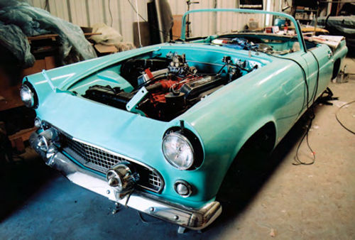
With the dash and electrical system installed, the rest of the reconstruction involved mounting the bumpers, the grille, and the headlights and tail lights, (Photo 8).If you will refer back to Photo 6 you can see where the exhaust pipes will exit through the round uprights that attach to the rear bumper.
That left installing the hood, the deck lid, and doing a lot of detail work inside the engine compartment. Those details include the weather stripping on the inside of the hood, the correct decals in the engine compartment, and all of the right components this car received at the factory such as the heater/vent tubes, windshield washer bottle, and power brake booster.
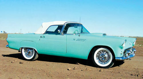
The last parts of this car to be tackled were the interior trim and convertible top. I don’t install convertible tops because it takes a lot of precise work and expert sewing to make a top look right. To be sure this top was as tight as a drum with absolutely no wrinkles or flaws I turned that task over to the professionals. The results were costly, but well worth the price. Photos 9, 10 and 11 are a few shots of the final product.
Some Surprises Encountered


I had a few surprises I can pass along, starting with the carburetor.
When the car arrived at the shop the carburetor was boxed in a secure container that listed the unit as having been rebuilt. I made the errant assumption (I actually know better than to assume) that I had a like-new carburetor. After several fits and starts to get the car to crank and run as it should, I removed the carburetor and found to my surprise that while the carburetor looked new on the outside no rebuilding had occurred inside the unit. I rebuilt the unit and solved the hard-to-crank and loss of power under acceleration issues.
Then there was an issue with the engine. The previous owner assured us the engine had been rebuilt by a reputable local shop (here I went assuming again). The problem was that the left exhaust indicated that a lot of oil was being burned. Blue smoke is a dead giveaway.
Exasperated, I removed the engine and delivered it to my machinist. (You saw his shop during the Project Charger series.) I quickly learned that although many of the internal parts had been replaced, no machine work was done to the block or heads. One large check later I had an engine I could depend upon.
Is there anything to be learned here? Just that the only way to know for sure about any part of your ride is to never, ever assume someone else is looking out for your best interest. Got a question? Send it along.
Resource
Project vehicle supplied by:
LPL Body Works, LLC
5815 Contented Lane, Amarillo, Texas 79109
lplbodyworks.com Paint and body repair DVDs


