
Building a Car In 30 Minutes
With Practice and a Script, Teams Quickly Assemble Model T’s Start With This Article, and You Could Do the Same
AS A PERSON interested in auto restoration, wouldn’t you like to be able to build the car that you’re working on now, from a pile of parts to running automobile, in under a half hour? This is a procedure that specially trained members of the Wisconsin Capital Model T Ford Club, as well as other “T” club members, have mastered through many hours of practice.
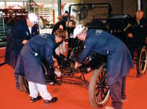
When putting the car together, the members of the Model T Assembly Team start with a bare frame sitting on sawhorses. The parts for the car are laid out in a specific arrangement. The sheet metal body parts are already painted, the interior is trimmed and the engine and transmission are already rebuilt and assembled, though out of the car.
Complete assembly of the car by team members requires about 25 minutes. Two Lifters and up to six Volunteers are enlisted to make the job more fun. Each Volunteer does one part of the assembly, so all helpers get a chance to participate.
Working With a Script
This quick-time Model T assembly procedure got added visibility when Ford asked members of the Wisconsin team to put on 16 demonstrations of their “T” assembly skills during the company’s centennial celebration in Dearborn, Michigan, in 2003.
Furthermore, to make sure things went smoothly in Dearborn, Ford scripted the whole assembly process as if it were a play and provided a stage so the team was elevated and easier for the crowd to see. Using a script also ensured that the announcer explaining the process to the public would be in synch with what the team members were doing at any given time in the assembly.
To get the public more excited about the project, volunteers were selected from the audience to assist the Model T buffs with the assembly. In the Ford script, there are four team members identified as T1-T4, six volunteers identified as VF1-VF3 and VR1-VR3 (the center symbol indicates front or rear), and two “lifters” identified as L1 and L2. The number of people can vary, but a minimum of six is required. It took many practice sessions to “script” the assembly process and writing the script also helped the team refine the assembly process. As they wrote down each procedure they followed, they saw ways to cut corners and speed the process. The script also gave them a better idea of what tools were being used in the process. By having more than one of a certain tool, the work involved could be streamlined.
The following script actually tells how to assemble the restored components of a Model T into a complete, running car. If you follow this script, you could form your own Model T Assembly Team and put on demonstrations of your own.
Or, it also could be used as a general guide for the restoration of a Model T Ford.
Assembling a Model T 1. Rear Axle Assembly & Installation
People involved: T1, T4, VR1 and L1 and L2.
Tools required: VR1—rear axle stand and 1/2-in. ratchet with 7/8-in. shallow socket. T1—one Model T Ford spark plug wrench. T4—one Model T spark plug wrench.
Special notes: This runs concurrent with operation no. 2.
Procedure: T1 and T4 start by elevating the rear axle. T1 instructs VR1 to install the axle stand. T4 and VR1 install the passenger side wheel and tighten it using a Model T spark plug wrench. T1 installs driver side wheel and tightens it using Model T spark plug wrench. T1 moves the rear frame stand to the back of the stage. T1 and T4 elevate the completed rear axle assembly. T1 instructs VR1 to move the axle stand to the rear of the stage. VR1 returns, taking a position on the stage to the front of T4. T1 and T4 elevate the drive shaft by using the radius rods. Then, they guide the axle assembly under the frame, up to the front frame stand. T1 and T4 elevate the back of the frame, using the rear bumper brackets. T4 instructs VR1 to remove the front frame stand. T1 and T4 continue rolling the axle assembly under the frame, with T1 guiding the drive shaft over the brake cross shaft and guiding the brake rods under the rear bumper brackets, until the rear spring is under the rear cross member of the frame. T1 and T4 lower the frame onto the spring. T4 installs the spring plates and starts the nuts. T4 instructs VR1 to tighten the rear spring clamp nuts using a 1/2-in. ratchet wrench with a 7/8-in. shallow socket. T1 rotates the ball cap to place the grease cup up and to position the bottom of the ball cap in front of the brake cross shaft. T1 attaches the brake rods to the brake cross shaft. T1 chocks the driver side rear wheel. Then, T1 moves the car’s engine, which is mounted on a stand, into place in front of the frame. T1 then provides L1 and L2 with lifting equipment.
2. Front Axle Assembly & Installation
People involved: T2, T3 and VF1.
Tools required: VF1—front axle stand. T2—one Model T wheel bearing wrench. T3—one Model T wheel bearing wrench.
Special notes: Runs concurrent with operation 1.
Procedure: T2 and T3 pick up the front axle and move it so that the spring is under the front cross member. T3 instructs VF1 to place the front axle stand under the front axle. T2 guides the frame onto the spring, while T3 elevates the wishbone. T2 installs the front motor mount bracket. T2 instructs VF1 to attach the spring plate and nuts. T2 installs and tightens the driver’s side wheel, wheel bearing, washer and nut using a Model T wheel-bearing wrench. T2 installs a cotter pin in the end of the wheel spindle. T3 installs and tightens the passenger side wheel, wheel bearing, washer and nut using a Model T wheel-bearing wrench. T3 installs a cotter pin in the end of the spindle.
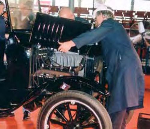
3. Engine Installation
People involved: T1, T2, T3, T4, L1 and L2.
Tools required: T1—U-joint alignment tool, 3/8-in. ratchet with 9/16-in. shallow socket and 9/16 open-end wrench. T2— 3/8-in. ratchet with 5/8-in. shallow socket.
T3—hole alignment tool and 1/2-in. ratchet with 7/8-in. shallow socket. T4— hole alignment tool, 5/8-in. box-end wrench and 3/8-in. ratchet with 9/16-in. shallow socket. L1—engine lifting arms. L2—engine lifting pipe.
Special notes: No volunteers used.
Procedure: T1 and T2 move the engine into place in front of the frame. L1 and L2 bring their lifting equipment onto the stage. T3 and T4 attach the lifting bar to the engine. T1 uses the U-joint alignment tool to check U-joint orientation. T3, T4, L1 and L2 will work together to lift the engine using the lifting arms and lifting pipe. T3 and L1 move into lifting position on the passenger side and T4 and L2 move into lifting position on the driver’s side. T 3 and T4 then position themselves on the lifting bars, close to T1. T2 starts the lifting and removes the engine stand once the engine is lifted. T2 stands at the front of the motor. He takes responsibility for controlling the radial and linear attitude of the engine by issuing commands to the lifters or by making his own adjustments. When the engine has cleared the firewall brackets, T2 passes control of the engine’s linear movement to T1. T2 continues to monitor the radial attitude of the engine. T1 guides the Ujoint into the transmission. Once the engine has engaged the drive shaft, T1 instructs the lifters to lower the engine into place. Once the engine is set in place, L1 and L2 move the lifting equipment and engine stand to the rear of the stage. They then exit the stage. T2 then secures the motor mount clamp using the 3/8-in. ratchet with the 5/8-in. shallow socket. T3 and T4 then install their respective rear motor mount bolts, using alignment bars if necessary. T4 makes the battery-to-starter electrical wire connection using the 5/8-in. box-end wrench. T3 attaches the fuel line to the frame and then moves near the driver’s side front tire. He holds the 1/2-in. ratchet with 7/8-in. shallow socket for T2 to use. T3 applies rearward pressure to the front axle to assist in making the wishbone-to-pan connection. Using the 3/8-in. ratchet with a 9/16-in. shallow socket, T4 connects the wishbone to the pan. T4 then instructs T2 to tighten the spring clamp using the wrench obtained from T3. T1 secures the ball cap using the 3/8-in. ratchet with a 9/16-in. shallow socket and a 9/16-in. open-end wrench.
4. Firewall Installation
People involved: T1, T2, T3, T4, VF2 and VR2.
Tools required: T1—3/8-in. ratchet with 1/2-in. deep socket and 7/16 box-end wrench. T2—3/8-in. ratchet with 5/8-in. shallow socket. T3—3/8-in. ratchet with 1/2-in. deep socket and exhaust wrench. T4—combination 1/2-in. and 9/16-in. open-end wrench. VF2—9/16-in. boxend wrench. VR2—no tools required.
Procedure: T1 picks up the firewall and places it on the frame of the Model T, taking care to place the steering bracket under the frame rail. T1 fastens the driver’s side of the firewall to the frame bracket using the 3/8-in. ratchet with 1/2-in. deep socket. He instructs VF2 to install the steering bracket fastener and tighten it using the 9/16-in. box-end wrench. T1 routes the driver’s side wiring to its proper locations. T1 attaches the magneto wire using the 7/16-in. box-end wrench, battery wire and taillight wire. The blue male/female connectors are used to make the proper connections. T1 installs the throttle control rod and spark control rod. Hairpin connectors are used to attach the rods to the control shafts on the steering column. T2 instructs VF2 to connect the steering arm to the drag link. T2 installs the spark control rod to the timer, securing it with a hairpin connector. T2 installs the timer to the motor and rotates the timing rod connection to a vertical position. Then, the bracket is secured by T2 using the 3/8-in. ratchet with the 5/8-in. shallow socket. T2 instructs VF2 to remove the spark plug wire nuts, attach the spark plug wires and reinstall the nuts. T3 routes the timer and headlight wiring to its proper location. T3 fastens the passenger side of the firewall to the frame bracket using the 3/8-in. ratchet with the 1/2-in. deep socket. T3 then attaches the choke wire to the choke bell crank on the firewall. Next, he installs the mixture control rod into the carburetor, pushes the generator wire onto the cutout and tightens the exhaust packing nut using the exhaust wrench. During this operation, T3 kneels down next to the firewall. T3 then installs the passenger side splash apron. T4 lays the exhaust pipe in the frame and instructs VR2 to fasten the muffler to the frame using a clevis pin with washer and a spring and hairpin connector. T4 installs the storage battery with the positive post to the front and makes the positive and negative connections using the 1/2-in. and 9/16-in. combination wrench. T4 instructs VR2 to install the rear hub and dust caps. T4 installs the driver’s side splash apron. T4 and VR2 install the spare tire carrier (without spare tire).
5. Body Installation
People involved: T1, T2, T3, T4, VF3 and VR3.
Tools required: T1—3/8-in. ratchet, 1/2-in. shallow socket, 3/4-in. shallow socket, 9/16-in. deep socket and large straight-blade screwdriver. T2—3/8-in. ratchet, 3/4 -in. shallow socket and 9/16- in. deep socket. T3—3/8-in. ratchet, 15- mm deep socket, 3/4-in. shallow socket and 7/16-in. shallow socket. VF3—3/8- in. ratchet, 1/2 -in. shallow socket. VR3— 3/8-in. ratchet, 15-mm deep socket and Model T spark plug wrench.
Procedure: T3 starts by positioning lifting board for T1 to grab. T1 and T3 lift the front of the body. T4 lifts the back of the body. T2 instructs VF3 to hold the firewall to body nuts. T2 then checks to make sure the spark and gas levers are in their “down” positions. Next, as the team lowers the body onto the frame, T2 guides the process with verbal commands, to make sure the body clears the steering column and that the firewall-tobody bolts wind up in proper alignment. The lifting team first rests the body on the frame in preparation of making the final connections between the body and firewall. T1 and T3 grab the body directly under the doors and elevate it. T4 instructs VR3 to remove the lifting board from under the passenger side of the body and place the board at the rear of the stage. T1 and T3 lower the body to the frame and engage the firewall. After the screws have engaged the firewall, T4 lowers the rear of the body, while applying forward pressure. T1 and T3 watch for proper alignment of the center bodyto-frame pins. T2 starts the firewall-tobody nuts. T2 instructs VF3 to install the front hub/dust caps. T1 and T3 tighten the firewall-to-body nuts using the 3/8-in. ratchet with the 1/2-in. shallow socket. T4 and VR3 install and tighten the rear body bolts using the 3/8-in. ratchet and 15-mm deep socket. T1 installs the seat and floorboards. T1 runs the ignition switch assembly through the dashboard.
6. Sheet Metal & Radiator Installation
People involved: T1, T2, T3, T4, VF3 and VR3.
Tools required: T1—Large straight screwdriver and 3/8-in. ratchet with 3/4-in. deep socket. T2—3/8-in. ratchet with 3/4- in. deep socket. T3—no tools required. T4—3/8-in. ratchet with 11/16-in. shallow socket. VF3—no tools required. VR3—Model T spark plug wrench.
Procedure: T4 and VR3 install the rear fenders, starting on the passenger side. T4 tightens the splash apron fasteners only, while VR3 steadies the fenders. T4 tightens the green battery disconnect knob. Then, T4 and VR3 install the turtle deck base, battery door and turtle deck. T2 attaches the passenger side fender to the brace and starts the eyebolt nut, while VF3 steadies the fender. T2 instructs VF3 to install 1/4-in. carriage bolts, from under the frame flange. They go through the fender and are then held fast with hand-tightened wing nuts. T2 hand tightens the eyebolt nut. T2 informs T3 when VF3 is finished installing the carriage bolts. T2 installs the hood clamp strip and hand-tightens it. T2 installs the passenger side lower radiator spring and cup mount. T1 installs the driver’s side front fender and driver’s side hood clamp strip and tightens all fasteners. T1 installs the driver’s side radiator spring and cup mount. T1 installs the driver’s side running board. T3 assists T2 with fender installation until VF3 is finished helping T2 install the passenger side front fender. T3 and VF3 then install the passenger side running board. T3 fastens the running board to the front running board bracket and front fender. He then instructs VF3 to fasten the running board to the rear running board bracket and rear fender. T3 instructs VF3 to enter the interior to install the steering wheel while T3 installs the ignition switch plate. T1 moves the radiator near the driver’s side front wheel. T2 places the radiator on the frame mounts, while T1 positions and tightens the radiator hose clamps using the large flat-blade screwdriver. T2 installs and tightens the radiator support rod by hand. T1 installs the driver’s side radiator hold-down and tightens it by hand. T2 installs the passenger side radiator hold-down and tightens it by hand. T1 brings the headlights over to the car and hands passenger side light to T2. T1 installs the driver’s side headlight, connects the wire and tightens the nut using the 3/8-in. ratchet and 3/4-in. deep socket. T2 installs the passenger side headlight in the same manner. T3 and VF3 get buckets full of water for the radiator. T1 installs the hood. T2 instructs VF3 to fill the radiator with water. T2 installs the radiator cap. T4 fastens the driver’s side running board to the front running board bracket and front fender and instructs VR3 to fasten the driver’s side running board to the rear running board bracket and rear fender. T4 instructs VF3 to tighten both rear fender eyebolts using the 3/8-in. ratchet and 11/16-in. shallow socket. T4 installs the spare tire using the Model T spark plug wrench.
7. Starting and Driving
People involved: T1, T2, T3, T4, VF3 and VR3.
Tools required: T1—no tools required. T2—no tools required. T3—no tools required. T4—Model T jack. VF2—no tools required. VR3—a smile and a wave.
Procedure: T1 instructs the driver to turn ignition on to the left. T1 instructs the driver where to set the spark and throttle. T1 cranks the engine over and operates the choke. After the car starts, the driver trims the spark and throttle controls for smooth running. The driver sets the parking brake and instructs T4 to remove the Model T jack. The driver instructs T2 to remove the wheel chocks. The driver invites VR3 to ride off the stage.
See This in Action
The Wisconsin Capital Model T Ford Club will be squaring off against other Model T assembly teams in a timed assembly competition during the Model T Centennial celebration in Richmond, Indiana, from July 21 to July 26. The timed assembly competition will begin on the 23rd and 24th with finals on the 25th.
For more on the Model T centennial, see the May issue. For more on the celebration in Richmond, Indiana, contact the Model T Ford Club of America by visiting www.mtfca.com or calling .


