How -to Diagnosing & Repairing Wiring, Pt. 2
We’ll Continue the Project by Replacing a Bad Wiring Harness. Then We’ll Review Some Troubleshooting Tips.
EDITOR’S NOTE: LAST month we looked into the conditions behind a silent horn and a “jumping” gas gauge on this 1955 Chevrolet project car. Then, while we were checking out the car’s intermittent taillights, we found that the rear body harness running under the driver’s side sill plates had been extended with the help of scraps of wiring and electrical tape. Although we ran Photo 6 last month showing this taillight wiring situation, we’ll repeat it again here and pick up our project at that point.
Making Proper Repairs
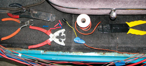
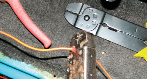
If the wires in the rear body harness had been in good condition overall, it would have been acceptable to repair the damage by splicing in a section of new wire to bridge the gap. This would be accomplished by cutting out the damaged section of wire and splicing in a new wire of the same size using crimp connectors, such as the smallest size buttconnector that can slip over the wires. The splices would then be made permanent by crimping the connectors in place using a proper crimping tool (Photos 7 and 8). After crimping, test each splice by gently pulling on the wires to ensure that they are snug.
Here is a tip when using crimp connectors:Ifthewires arestillloosein the smallestsize crimp, you can improve the fit by stripping the wire song and then folding the bare wires back on themselves to make a more snug fit inside the connector.
For Project 55, the wires were carefully inspected from end to end, which required removing a lot of electrical tape to expose the wires. The overall condition of the vinyl wire insulation was very poor with many nicks and cracks in the insulation and the wires were very brittle, so the wiring harness needed replacement. High-quality replacements are available for many vintage cars and are a great way to go. There also are good do it-yourself wiring kits to build your own wiring harness. In my case, I already had the correct contacts and wires in hand, so I chose to build my own wiring harness. I replaced the wires for the taillights, brake/turn signal lights, gas tank gauge, and dome lights from the body wiring connector all the way to the lamps at the back of the car. I chose to use 18-gauge wires, which are one size larger than original. New wiring standards recommend a larger size (smaller gauge number) wire than was used in the mid-’50s, so upsizing the wires provides some nice peace of mind.


While the driver’s side door sills were apart and the wiring covers off, I vacuumed out a significant amount of dirt and debris, and then treated the surface rust with Eastwood’s Rust Converter followed by two coats of their Rust Encapsulator. As a preventative measure, I disassembled and inspected the passenger side door sills. They looked good, but I still applied a coating of Rust Encapsulator to keep the rust at bay. After the new harness was routed (Photo 9), the interior was put back together. The result— everything is working great.
And what about the bad headlight switch we discussed last month? It worked perfectly for several months, but was eventually replaced to fix the dash lights.
Some Tips and Techniques
A good voltmeter is one of the most important tools you can have in your toolbox because it can tell you a lot about the health of the electrical system. Digital voltmeters have become very affordable, with a decent basic meter costing less than $10. In addition, some useful troubleshooting tools can be homemade (Photo 10).
When troubleshooting a device such as a fan, light, motor, etc., measure the voltage between power and ground as close to the component as possible. Usually you can measure at the input terminals or a plug near the component. Unless absolutely necessary, do not stick a probe through the wire insulation because that damages the wire. If you must penetrate the insulation, be sure to put electrical tape over the hole to keep moisture out.
Continuity measurements show the quality of an electrical connection, such as measuring between the alternator and chassis ground, or between the battery and starter. Set the meter on the lowest Ohm(resistance)setting. Good continuity measurements will always be nearly zero. Star washers are pretty handy to fix bad grounds.
Resistance measurements are used when testing temperature sensors, the quality of grounds, and gas gauge sending units. Be sure to keep your fingers away from the lead tips when measuring resistance or continuity, otherwise it will give you inaccurate readings!
If you have trouble making sense of the wiring diagram and following all those little lines across the page, try this trick. Make enlarged photocopies of the relevant pages and highlight the wires in your circuit using different color highlighter pens. It makes a great visual aid. Just don’t do this in your service manual or it will become unusable over time.