How -to Diagnosing & Repairing Wiring, Pt. 1
This Project Car Has a Silent Horn and Erratic Lights & Gauges. So,We’ll Check to See What’s Gone Wrong.
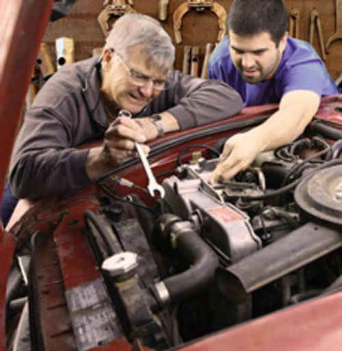
OUR PROJECT VEHICLE is a 1955 Chevrolet older restoration that was used as a daily driver for years, and all that daily use had taken its toll.
The car previously had been rewired under the hood and dash with a replacement wiring harness, but most of the instruments and controls didn’t work properly. In fact, the generator light and temperature gauge were the only instruments that worked. The Chevy’s horn was silent, and the interior, dash and taillights were intermittent.
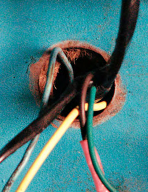
Follow along as we diagnose and remedy the horn, gas gauge and lights (Photo 1).
Plan Your Work
The first step is to develop a game plan,starting with a really good wiring diagram, like you’ll find in a factory service manual (Photo 2).
A good quality wiring diagram is loaded with vital information needed for troubleshooting, such as the general wire layout, wire colors and sizes, and wire connections.
Some people find that wiring diagrams are intimidating to read, especially on the new generation of computer- and gadget-laden cars and trucks that have more wiring than a Mercury spacecraft.
How can you make sense of it all? Well,it’s actually pretty straight forward if you break it down into the individual systems or circuits.
Auto wiring interconnects many different systems with the wires routed together into common bundles. The trick is to diagnose each system separately.Thankfully, the wiring on a ’50 sera car is relatively simple.
Getting Started

Armed with the wiring diagram and a good flashlight, I dove in, under and around Project 55. The under hood wiring was nearly new and the installation was reasonable, although there were no grommets in the firewall or other places where the wiring passed through the body (Photo 3). Grommets keep smoke and fumes out of the interior and keep the wire insulation from chafing against the body. Without grommets, you are asking for a short circuit. If you are lucky, you will blow a fuse and ride home in a tow truck. If you are unlucky, you will ride home in the tow truck after the fire department puts out the flames from your automotive fire. Enough said.
Under the dash the new wiring harness had been installed and routed well, but much of the old wiring had been left behind, along with a lot of unused aftermarket stereo wiring. There were a lot of deadheaded wires plus there were two mystery switches that were not connected to anything. Several hours were spent carefully tracing and removing old unused wires. I used extreme caution to prevent accidentally cutting a wire that is actually needed for something! I have encountered this problem on a number of project vehicles; usually the excess wires were left behind from previous accessory installations or emergency repairs.
Horns and Relays
The horns did not work on project 55, and, in fact, were not hooked up at all. As it turned out, the horns were from a newer car and didn’t have the right terminal connections.
Even more puzzling was the location of the horn wires. They were nowhere to be seen, and there were no unattached wires coming from the wire bundle. It took some head scratching and several reviews of the wiring diagram to solve the mystery.
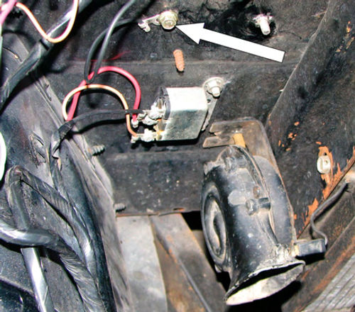
In 1955, Chevrolet used 16-gauge black wires for the horn circuits from the relay to the horns. It appears the wiring installer incorrectly assumed that black meant ground. Based on that assumption, the wires were routed to the wrong side of the core support, then grounded to the body with small bolts (Photo 4).
I verified that these were the proper wires by disconnecting both horn wires from the body and measuring continuity back to the horn relay output. This is where having the correct wiring diagram comes in handy. A generic wiring diagram would not have done the trick.
The next step was testing the horn relay. The relay is an electrically activated switch that turns on when the driver pushes the horn button. Depressing the horn button grounds the control wire, activating the relay and allowing electricity to flow to the horns (Illustration 1).
In a properly functioning system the relay should “click” when the horn but ton is pushed, whether the horns are connected or not. In this case that didn’t happen. Using my voltmeter, I verified that there was 12 volts available to the relay (red wire). I momentarily grounded the tan (switch) wire with a jumper wire and the relay clicked like it was supposed to. This indicated there were problems in the column or under the dash. Next, I temporarily connected the horn wires to the horns using jumper wires and repeated the test. The horns should have honked, but did not.
I measured voltage at the relay output lug (black wire) and found very low voltage, indicating that the relay had failed. It probably was ruined the first time it was activated with the output wires shorted to ground.
Moving on to the steering column, I disconnected the tan horn wire from the column and measured continuity between the column side of the wire and ground. In a properly working system, pushing the horn button will make the reading change from open to ground. On this car the horn wire measured as an open circuit, regardless if the horn button was pressed or released, indicating a problem in the horn button or column. I chose to leave the horn switch alone for now, and fix it when I rebuild the steering column. As a temporary fix, I connected the horn wire to an unused toggle switch under the dashboard edge.
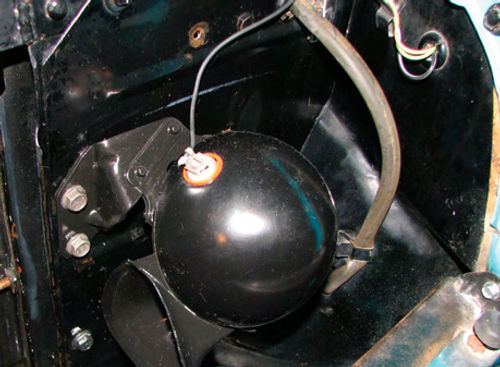
I purchased a restored set of original horns and brackets on eBay, which were installed on the core support (Photo 5). I also purchased and installed a new horn relay, which brought the system into working order.
Having the switch under the dash edge is a minor nuisance but is adequate for a temporary fix.
The Case of the Jumping Gas Gauge
The gas gauge in Project 55 worked, but it was erratic and unreliable. The needle seemed to have a life of its own, jumping sporadically to full and back again. The problem could have been the gauge itself, the sending unit, the interconnect wiring, or a bad ground.
So, what is the best way to isolate gas gauge problems?
An electric gas gauge is basically a specially designed ohm (resistance) meter. The sending unit is a variable resistor connected to an arm and a float ball. As the fuel level moves down, it changes the resistance through the sending unit. The gas gauge measures the resistance, which is shown to the driver as a fuel level (Illustration 2). In this era, General Motors used 0-30 ohm resistance sending units.In 1966, GM switched to 0-90 ohms. Ford used 73-10 Ohms in this era. There are about a half-dozen common sending unit resistances in use, which can be found in the shop manual or on the Internet.
One very important thing to keep in mind is the gas gauge measures ALL of the resistances in the circuit from the gas gauge through the wires, sending unit, and the return path to ground. If there are any bad grounds or corroded connections, they will make the gauge read improperly. These resistances all add up quickly and 30 ohms is not very much. I have fixed several gauges that had high resistance between the gas tank and the car body due to a poorly grounded gas tank. Dirt, corrosion or paint buildup between the tank and the body are not uncommon. In fact, the shop manual lists high resistance as the most common cause of gas gauge faults.
I prefer to start troubleshooting from the gas tank, since most problems seem to occur at the sending unit. Also, it is usually much easier to get good access to the connections there.
To start, make a good visual inspection of the wiring, tank and sending unit. Next, measure the resistance between the face of the sending unit and a clean body ground (not the gas tank). If the resistance is more than an ohm, the gas tank is not properly grounded and it will affect the gauge reading. Adding a ground wire between one of the sending unit screws and a good body ground will usually do the trick.Don’t forget to apply a light coating of dielectric grease to the connections to keep the corrosion from coming back.
Still Not Working? Remove the wire from the sending unit post. You can connect it to a properly working (and grounded) spare sending unit, and test by moving the float arm through its range of motion. Unfortunately, most people don’t have a spare sending unit lying around. If your gauge is the 0-30 or 0-90 ohm type, connect the sending unit wire to ground with an alligator clip. The gas gauge should read empty. If it doesn’t, the problem is gauge power, the gauge itself, or the wiring.Leaving the wire disconnected should indicate more than full. Measure the resistance of the sending unit to see if it corresponds to the approximate fuel level. If the sending unit readings are out of range the sending unit will need to be replaced.
Another method is to buy a variable resistor from an electronics store to use as a test aid. Adjust it to the desired resistance value and check the gauge. This allows for testing the entire range of the gas gauge.
For Project 55, I was lucky and found the problem when I did the visual inspection. The gas tank and sending unit are nearly new and well grounded. However, the nut on the sending unit post had vibrated loose, so the wire was floating on the post. The connector was also corroded, so I replaced the terminal and applied a thin coating of dielectric grease. I reassembled it using a star washer to keep the nut from coming loose again.
The gas gauge is now working properly and appears to be reasonably accurate.
They’re Off, They’re On, They’re…
Project 55 had intermittent taillights from the day she first rolled into our garage last spring. The taillights didn’t work half of the time, but could be coaxed to work by opening the door, jiggling the lightswitch, closing the door and checking again. This trick worked most of the time, although we didn’t drive the car at night very often due to this problem. During the summer months it was not an issue, but when fall came this needed to be fixed, especially since the problem was getting worse.
The car definitely had a bad headlight switch because the dash light rheostat was erratic and the light stem was loose. Certainly that must be the problem, right? Astempting asit was to just install a new switch without troubleshooting first, I took a few extra minutes to confirm the problem with a voltmeter. That turned out to be a very good decision, because the real cause was much different than it first appeared.
With the headlight switch on and the taillights not working, I measured the voltage between the switch terminal for the parking lights and chassis ground. Much to my surprise, there was 12 volts at the switch.

Obviously, the problem was someplace between the switch and the taillights. Using the wiring diagram, I traced the circuit from the switch back to the lights, identifying the under-dash connector where the Fisher body wiring harness plugs into the Chevrolet main wiring harness. Using my voltmeter, I carefully inserted the lead into the back side of the socket onto the taillight pin and the other lead to chassis ground. There was 12 volts at the plug, indicating the problem was in the rear body wiring harness.
Uncovering the Problem
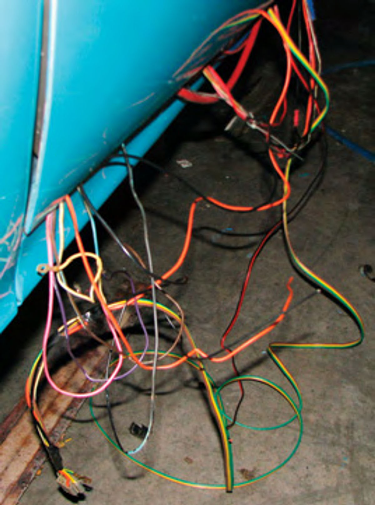
To confirm the diagnosis, I temporarily strung a wire outside the car, running from the wiring harness plug under the dash to the trunk, where I Plugged it into a license lamp connector. As expected, the tail lights came on. This indicated the taillight power wire was broken or damaged someplace between the dash connector and the taillights. Exposing the wiring harness required pulling the driver’s side kick panel, the front and rear door sill plates, and the wiring tray cover. Once the wiring was exposed, a number of dirty secrets were exposed (Photo 6).
This was the original 1955 wiring harness, and at some point it had been removed and reinstalled. At that point, apparently, the harness came up short, likely the result of the harness being incorrectly routed.
Rather than re-route the harness properly, the wires were cut and extended about three inches using scraps of wire and electrical tape. This is a poor practice, especially since the spliced wires were undersized and the ends were twisted together, leaving the connections vulnerable to corrosion and damage. After a dozen years the wires had oxidized and failed to make good contact. I could make the lights work by wiggling the wires, although the splices got extremely hot because of the high resistance.
While it first appeared that the headlight switch was the problem, it was actually the vibration from opening and closing the door that made the taillights work.
Next,we’ll build a new wiring harness for our project car and then discuss some tools and techniques for successful wiring repairs.