Replacing Differential & Axle Seals
Over Time, These Seals Will Need Replacement On Your Ride. Fortunately, the Job Is Done With Common Tools.
ONE DAY AFTER parking my vehicle in the garage I noticed that funny smell of differential grease. It wasn’t too long ago that the rear axle seals had been replaced, could one have failed? There was no sign of leakage evident on either of the brake shoe backing plates, and had there been, that would indicate neglect on my part for allowing it to go unnoticed for so long.
As it turned out, grease had been slinging from the differential pinion seal, and was cast on the underside of the vehicle.
There were several routine maintenance tasks that needed to be done at the time such as changing the transmission fluid and rotating the tires. These required the vehicle to be elevated, so it was the perfect time to investigate the problem.
Knowing that a replacement pinion seal would certainly be needed, a phone call was placed to the local parts store to check on its availability. It wasn’t long before they asked “what’s the ring gear’s diameter?” I didn’t know the answer to the question, although it’s not too difficult to find out. The vehicle that’s in question is a 1987 El Camino. The rear cover could simply be removed and a measurement taken, or if you have a factory service manual, the axle housing number can be referenced and translated.
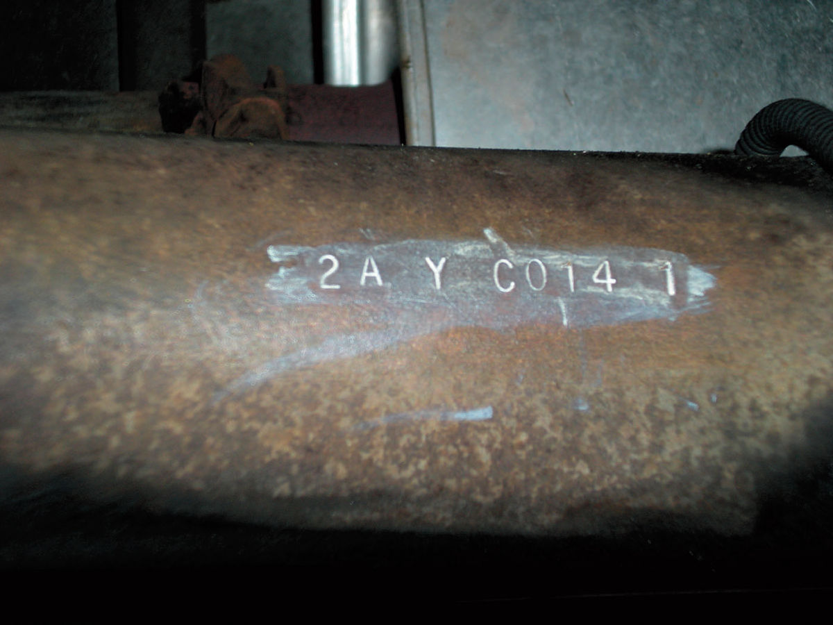
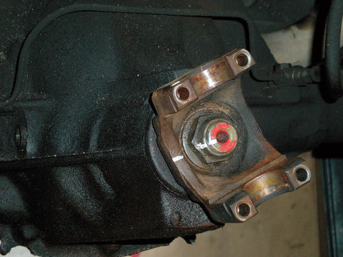
After raising the vehicle, jack stands were placed under the frame rails behind each front wheel and under each rear axle housing tube. On this vehicle the axle housing number is located on the right axle tube, facing forward, and almost centered on the axle tube. The code for this vehicle is 2AY C014 1 as seen highlighted in white in Photo 1. It identifies it as being from an El Camino (non SS), with a 71 ⁄2” ring gear. It also supplies information such as the manufacturer of the differential, its ratio, tooth count, whether or not it’s limited slip, and brake type. This is worth remembering if you ever need to know any of the specifics.
Sure, on a few vehicles out there someone may have changed the gear ratio, and if the vehicle has been fitted with traction bars and huge rear tires, it’s guaranteed. But for the most part, it’s handy information.
Before going into town, I decided to get the tire rotation out of the way and get a quick look at the brakes while doing so. While the brake lining thickness was fine, the shoes on the right rear were grease contaminated from a leaking axle seal. The rear axle seals had been replaced a couple of years ago along with new axles and bearings on both sides. There was nothing remarkable about the task at the time. Anyway, that seal will have to be replaced as well, and a close inspection will be made to try and determine what caused it to leak relatively soon after being replaced.
Starting With the Axle Seal
The axle seal will be replaced first followed by the differential pinion seal. The wheels had already been removed, and the right brake drums slid off. Removing the differential cover is the first task. A catch pan is placed underneath and all but two bolts are removed, one remaining on each side of the cover. A 1/2” socket on a 3/8” ratchet is the best choice to remove them.
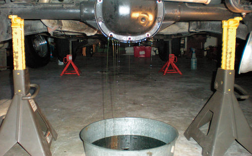
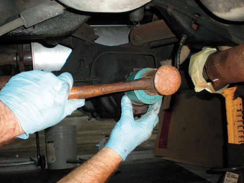
Finally, loosen each of the two remaining bolts several turns and then break the seal between the housing and cover as seen in Photo 2, allowing the grease to drain. Once the “rush” is over, remove the two remaining bolts and set the cover aside.
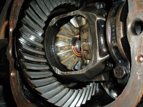
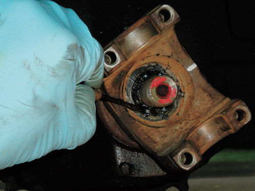
Next a 5/16” wrench will be needed to remove the pinion shaft bolt. The pinion shaft is the steel pin located in the center of the carrier that supports the small pinion gears, and sits between the axle side gears. If you look closely in Photo 3, what appears as a vertical steel pin is the pinion shaft. Copper in color and just to its left is the C-lock for the left axle. We ultimately will be removing the one opposite it.
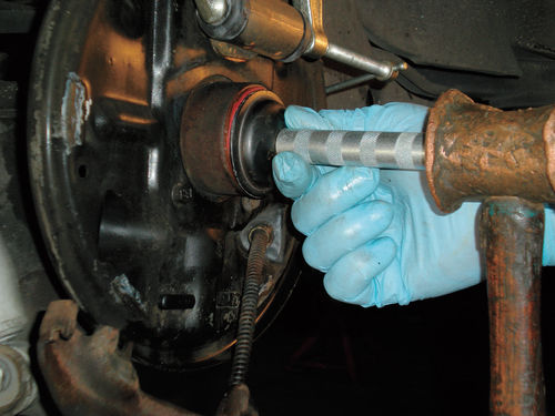
The pinion shaft bolt must be facing toward you, and it’s easiest when the pin is positioned at a slightly downward angle. Most likely you will need to reach your hand over the carrier and push the pin toward you with your fingertip. Usually it will slide out easily, although this one was a bit sticky. Don’t remove it completely; leave it engaged with the small pinion gear and carrier. Photo 4 shows what I am referring to. Should it begin to slide out on its own, push the pin back in, leaving just enough exposed to grab onto and roll the driveshaft slightly to lessen the pin’s angle, then pull it out again as before. Should it be removed completely, the small pinion gears may fall out of position, although it’s not a big deal to reposition them. (Last month John showed us what to do if the pinion shaft bolt breaks as you’re attempting to remove it.)
Once the pinion shaft is removed far enough it will allow the axles to be moved inward. Push the right axle flange inward, and the retaining C-lock will fall off the end of the axle. Retrieve it from the bottom of the differential case. Now the axle can be removed. If for some reason the axle seal was to be reused, care would be taken during removal not to drag the axle over the seal lip. This seal is coming out, and probably the best tool to remove it is the axle itself. Photo 5 shows using the tip of the axle tucked under the lip of the seal to pry it out. Notice the brake shoes have been removed. This is not necessary for seal removal and replacement, but the shoes were grease contaminated, and it also makes the photo less cluttered.
With the old seal out of the way, the seal bore was cleaned and inspected looking for possible marring or other damage that could have let fluid leak around it, but no damage was found. Synthetic differential grease is used in this vehicle, and while it has the same weight rating, it appears thinner than traditional 80W-90 weight grease. Synthetic engine oil has a reputation for finding its way out of an engine’s crankcase more easily than traditional oil, so possibly the same applies here.

The axle and bearing were inspected and looked fine as anticipated. My conclusion was that most likely I distorted the last seal during its installation. The lip of the new seal was coated with an assembly lubricant, and a light coating of sealer was applied to the steel perimeter edge of the seal before it was installed. There are a couple of things to notice in Photo 6. Visible in the top of the photo is a C-clamp placed over the wheel cylinder, this is for added security. Some vehicles have stops that limit wheel cylinder piston travel, this one doesn’t. The main focus, however, shows using a seal driver for installing the seal, but a large socket will work just as well. The seal should be installed flush with the edge of the housing and the axle can now be replaced. Care must be taken to avoid dragging the axle over the seal’s lip, as this will very likely damage it.
Insert the axle into the axle tube keeping it centered within the diameter of the seal. Once it has entered the axle tube the leading edge of the axle will actually end up resting on the bottom of the housing as it is sliding inward, while the flange is supported keeping the weight of the axle off the seal. When the axle reaches the carrier it will stop. While still supporting it, the flange is then manipulated to lift the end of the axle so that it will engage with the side gear. Slide it in until it stops. Through the center opening in the carrier, the retaining C-lock is slid into the axle’s groove and the axle is then pushed outward slightly, securing the C-lock in the recess of the side gear. The pinion shaft can now be slid back into position, and the pinion shaft bolt replaced. The torque specification for it is listed in the service manual at 15-25 foot pounds. Personally, I’d say that 15 pounds would seem more than adequate. In some instances it may be necessary to move the other pinion gear slightly in order to fully insert the pinion shaft. The rear cover is then cleaned, and if the gasket is undamaged it can often be reused. The cover bolts are also listed as requiring 15-25 foot-pounds of torque, and they were replaced using a crisscross pattern. Keep in mind that torque specifications apply to clean, lightly oiled threads. A build-up of dirt or other foreign material will create resistance, and you will obtain a false reading. The threads in this differential housing had an accumulation of old silicone sealer, so a thread chaser was used to clean them.
So What About the Brake Shoes?

CRC Industries makes a product called “Brakleen;” you may be familiar with it. It claims to remove grease, brake fluid and other contaminants from brake shoes and pads. The shoes were sprayed with the product and seemed to clean up OK. The backing plate, brake drum, springs and other hardware were also cleaned and the shoes were reinstalled. Had the shoes been badly saturated they would have been replaced. In decades past it always was the rule to replace grease-contaminated brake linings, as there wasn’t a reliable way to completely remove grease from the friction material. I will report back on how well the Brakleen performs in the long run and if the linings stay clean (CRC Industries: crcindustries.com).
Now would normally be the time to replace the differential grease, but the pinion seal is coming out next, so that will wait until the job is finished.
Making Reference Marks
It never hurts to index the drive shaft to the mounting flange. This will eliminate the possibility of a vibration due to an unintended change in their alignment.
A 7/16” box wrench is used to remove the four driveshaft retaining bolts and straps. The universal joint is then gently pried forward, freeing the driveshaft from the flange. A piece of masking tape was wrapped around the universal joint cups to retain them. The driveshaft can either be secured up and out of the way or simply removed and set aside. On this vehicle the drive shaft can actually rest on top of the exhaust pipe and be secured there. If you remove it, be prepared with a catch pan in the event you lose some transmission fluid. It usually won’t be much, but that depends on the vehicle as well as its resting angle.
The Pinion Seal
While the seal replacement itself is straightforward, the concern is with maintaining the proper preload on the pinion bearings, and the flange tightness determines that. The procedure as described in the factory shop manual for this vehicle is simply to mark the relationship of the components, disassemble and replace the seal, then replace the components in their original position and tighten the nut slightly beyond its original reference mark. Well, that’s the condensed version.
Clean and remove any dirt or grease from the flange, its retaining nut, and pinion threads, then mark the relationship between these three components as seen in Photo 7.
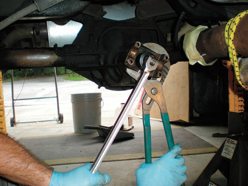
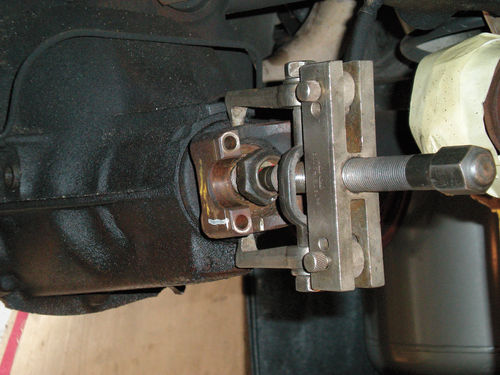
While white paint shows up well for photos, each component was also center punched as insurance in the event the paint came off during the procedure. Count, and write down the number of exposed threads on the end of the pinion. This is a good reference to have, especially if the nut is tight-fitting, and it’s helpful during reassembly. In this instance the differential grease had already been drained; had it not, a pan would be placed under the flange to catch any escaping grease. A 11 ⁄4” sixpoint socket is fit onto the breaker bar. While holding the flange with a large pair of slip joint pliers, the long breaker bar was used to initially loosen the retaining nut as seen in Photo 8. Once loose, a 1/2” drive ratchet finished the job. The flange may simply slide off, but sometimes a puller will be required. There are special pullers as well as holding tools for performing this service, but as shown in Photo 9, a good two-jaw universal puller will also work. Thread the nut back on a couple of turns for a safety measure, should the flange release suddenly. Keep in mind that if you don’t own a puller, many auto parts stores will now loan tools (with a deposit) for you to install the parts you buy from them.
A Close Inspection
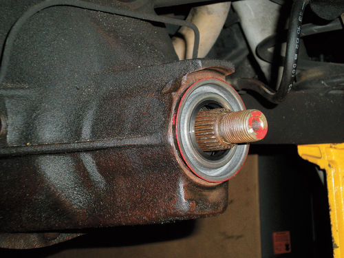
With the flange removed, it’s completely cleaned and inspected, being careful not to remove the reference mark. Pay close attention to the surface the seal rides against. It should be smooth and free of any grooves. Also inspect the drive splines for wear, and look for any other damage. If it’s damaged or significantly worn, replace it.
Out of curiosity I placed a phone call to the local Advance Auto Parts store to ask if a repair sleeve is offered that would slide over the (potentially) damaged sealing area of the flange. Such a sleeve is made to repair worn engine harmonic balancers, so I figured that possibly one is offered for driveshaft companion flanges. However, according to the clerk I spoke with, a flange sleeve is not available. But should the need arise, I would certainly call several of the other suppliers to make certain a sleeve is not available before purchasing a replacement companion flange.
Seal Removal and Replacement
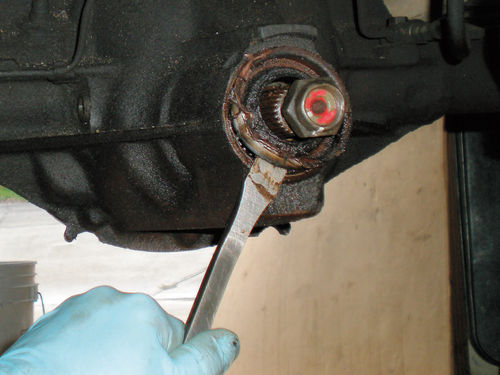
There are several methods and tools that can be used to remove the seal, but the easiest method is to collapse the seal inward from the side, and then pry it out. I chose an old screwdriver to catch the edge of the seal, and by striking it with a hammer, began the process. If the screwdriver accidentally slipped, it will do considerably less damage to the pinion threads or housing than a sharp chisel. Obviously you don’t want to beat up on one of your good screwdrivers, so choose one you might use for opening and stirring paint. In Photo 10 a pry bar is used to finish removing the seal.
With the seal removed, the seal bore is cleaned and inspected. Scrape out any old sealer, and if there are any burrs, remove them with a file. Next assembly lubricant is applied to the lip of the new seal, and a sealer is applied to the steel perimeter edge. The seal is then positioned squarely in the seal bore as shown in Photo 11.
This is a large seal, almost 3” in diameter, with a splined shaft protruding through the center, so unless you have a 3/4” drive socket set, and possibly a deep socket at that, you will probably have to come up with another option to install it. Of course they make a special seal installer for the task, but if you can’t find one locally, you can make one out of some PVC plumbing fittings that have the proper diameter. With your seal in hand, look around in your local hardware store or home improvement center in the plumbing section. You will find PVC fittings are inexpensive, and by combining a couple of pieces you can make a seal driver. Photo 12 shows several 2” PVC fittings that have the proper outside diameter needed for this seal. These represent a total cost of less than $5. Starting from the left is a 2” female adapter with a clean-out plug threaded in; a cap; and a 2” coupler. The coupler is an option if the extra depth is needed, and something as simple as duct tape can be used to secure the pieces together. A belt sander or file can be used to level out the top of either the threaded plug or cap to make a better striking surface.
Looking around in my tool box I found a cup from an old ball joint press to use (Photo 13). The seal is driven in until the edge is flush against the housing. The seal contact surface of the companion flange is coated with assembly lubricant then the reference mark on the flange is lined up with the mark on the pinion threads, and the flange is slid on as far as it will go. A small cavity of about 1/8” will remain from the end of the splines to the height of the flange. To avoid the possibility of grease finding its way out through the splines, fill this area with a non-hardening sealer, like Permatex Type A as seen in Photo 14, then replace the washer and nut. When the number of exposed threads approaches the number first recorded, pay attention to the indexing mark on the nut. Continue to tighten the nut until the marks are lined up, and then tighten until the mark on the nut goes 1/16” beyond the mark on the pinion.
The Torque Wrench Method
This method is worth knowing, as it is referenced for many vehicles, including my ’66 Malibu. Had the companion flange needed replacement, this method would have been required.

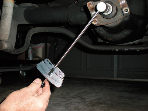
Count, and write down the number of exposed threads on the end of the pinion. If you anticipate reusing the flange, make the same reference marks as we did in Photo 7 to aid in reassembly. Once the driveshaft has been removed, a 1/4” drive inch-pound torque wrench is used to measure the torque required to rotate the pinion nut with the wheels and brake drums removed. To accomplish this two step-up adapters are used, a 1/4”—3/8” drive, followed by a 3/8”—1/2” drive. Now the 11 ⁄4” socket will fit the wrench. The differential is rotated by pulling the wrench as seen in Photo 15, and the amount of torque required to do so is 4 inch-pounds. Usually there isn’t enough room to make a full rotation with the torque wrench, so reposition the socket and take several readings to verify the reading is consistent.
Just to be on the safe side, take all the torque measurements while rotating in the same direction, either clockwise or counterclockwise. This measurement is the combined preload of the pinion bearings, carrier bearings, axle bearings, and even the seal. The information is recorded and will be used during reassembly.
If you own a click-type 1/4”-drive torque wrench, it probably won’t work. The one I own starts at 30 inch-pounds, far greater than the 4 inch-pounds we recorded. You will need a torque wrench that will register readings of anything greater than zero. A deflecting beam type and most dial indicator torque wrenches will work.
Either of these torque wrenches could be located and purchased through Snap On as well as the other professional tool suppliers. But I was curious and did a Google search on a deflecting beam 1/4” torque wrench, and Amazon was one of the first listings found. They sell one made by KD Tools for $39.75, and it’s manufactured in the US. The measurement range is 0—60 inch-pounds. Most interesting was a quick read of the reviews, as it only took a few seconds to find someone who had purchased it for checking pinion bearing preload, and there were several others that mentioned the same. And in case you’re wondering, the one seen in the photo was purchased from Amazon.
Follow the same assembly procedures previously outlined and while tightening the pinion nut, pay attention to the number of exposed threads. When the nut begins to tighten, and the thread count approaches the number recorded before disassembly, take another reading with the torque wrench. Verify the reading by repositioning the wrench and checking again. Continue gradually tightening the nut in small increments, using the 1/2” breaker bar and slip joint pliers. Proceed slowly, rechecking the torque often, as over tightening may collapse the pinion bearing spacer too much. One Chevrolet publication stated that “as little as 1/8 turn can add 5 additional inch-pounds of drag.” When a torque reading of between 3-5 inch-pounds greater than the initial value is established, you’re there. This is to compensate for the additional drag of the new seal.
Finishing Up the Project
The manual indicates the differential should be filled to within 3/8” of the fill plug hole. This roughly translates to reaching your little finger in through the hole and being able to touch the grease. As it turns out, this differential holds just over three pints of grease.
The tape was removed from the universal joint of the drive shaft; the reference marks lined up and the bolts and straps replaced securing the drive shaft. The torque specification for these bolts is 12-20 foot-pounds. The brake drums and wheels were replaced and secured. Lug nuts were torqued in a “star pattern” to 80 foot-pounds for 7/16”-20 studs, and 100 foot-pounds for 1/2”–20 studs.
Before removing the jack stands and lowering the vehicle to the ground, there’s the issue of slung grease on the underside. Mineral Spirits was applied using an inexpensive spray bottle, and wiped down with paper towels for the initial cleaning to remove the heavy stuff. Then a solution of Dawn dishwashing soap and hot water was liberally applied and scrubbed with a stiff brush.
A rinse with the garden hose finished the task. No doubt this is the dirtiest part of the job, and took about as much time as the repair itself. This will eliminate the differential grease odor, and avoid attracting dirt to the area. It will also make it easier to determine if there is any future leakage.
All that remains is to lower the vehicle and take it for a road test. Keep in mind that it may take several weeks to determine if any grease is leaking and the brake drum will need to be removed to inspect the axle seal. If there is no leakage found at that time, the book can be closed on this repair task.


