Removing a Broken Bolt
The Break Had Taken Place In a Very Hard-to-Reach Location. So Several Approaches Were Tried on the Part.
RECENTLY I NOTICED a noise coming from the rear end of my 1986 Chevrolet Caprice, and determined it was time to replace the axle bearing. Considering that neither bearing had ever been replaced in the vehicle’s history, that’s not bad. Oh I have replaced an axle seal here and there, but at almost 280,000 milesthe bearings were still the original. I know that because the car has been in our possession since the odometer turned 55,000 and prior to that it belonged to my father-in-law.
It Should Have Been an Easy Job…
This Is not a particularly difficult task— remove the differential’s rear cover; drain the grease; remove the pinion shaft retaining bolt;slide the shaft partially out and you’re on your way.
But on this occasion there was an unexpected surprise.
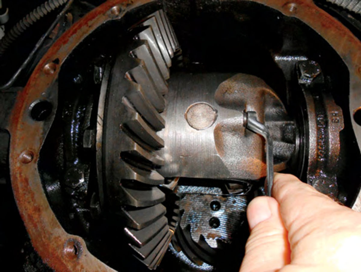
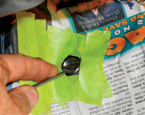
Photo 1 shows the rear cover removed, and the retaining bolt being loosened so the pinion shaft could be slid out. Having done this procedure many times, I knew something was wrong when after initially loosening the bolt, it momentarily bound and then freed up again. There was no question in my mind…the bolt had broken.
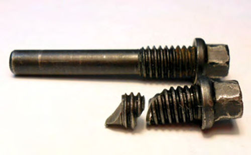
Once completely threaded out, a portion of the threads about 3/8” in length was removed, leaving well over two thirds of the bolt stuck inside.
Next came the challenging task of retrieving the broken bolt from deep within the case.
So where do you start? Sometimes you can get lucky, and with a simple pick tool spin out the remaining broken piece. What I am referring to is a small,straight pick, usually sold in a package with four different configurations. Probing down into the hole, the broken edge was found with the point of the pick. Trying to rotate it counterclockwise seemed to be working. A broken piece was definitely threading outward, so this appeared to be my lucky day.
But Photo 2 shows what was removed to this point, compared to what should have come out.
Studying the break, it appeared that all of the threads had been successfully removed, but the smooth pin portion still remained. Again the pick tool was used to probe around and try to spin the remaining broken piece, but it was wedged solid. Normally the pinion shaft will have some free movement even with the retaining bolt secure, but it too was wedged tightly in place. Most certainly this was due to the broken bolt, so I tried tapping gently on the pinion shaft with a lead hammer, and even used a pair of needle nose Vise-Grip pliers to grab the pinion shaft in between the gears and try to rotate it. The shaft is hardened, so there was little concern of marring it. If it had been slightly damaged, a stone could be used to dress it off.
Sending In Another Bolt
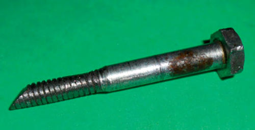
Finally, an old 1/4” bolt was customized for the job. The threads were smoothed out (just so they wouldn’t get hung up on the threads inside the case) and then the angle of the break was duplicated on the end of the bolt. Photo 3 shows the result.
It was then inserted into the hole and rotated until it lined up with the break. Tapping again on the pinion shaft while trying to rotate the bolt finally freed things. The broken section would now rotate, and the pinion shaft had the back and-forth free play it normally would. Being able to rotate the broken portion of the bolt was a step in the right direction, but how to get it out was still an uncertainty. There were no threads remaining, so it should easily clear the hole, but there was no way to grab onto it. I generally take all the time in the world and then some before making a decision on how to proceed, and this was no exception. There were a few ideas in my head, but I decided to contact my friend Don in Connecticut and get his take. He had only recently retired, closing up his auto repair business, and I consider him to be the most knowledgeable person I know when it comes to car problems and repair tactics.

Don explained that a method he had used successfully was to employ an arc welder and welding rod to retrieve the broken piece. Wrap the welding rod with tape, leaving only the tip of the end exposed. This would prevent the rod from arcing to the threads. Insert the rod into the case until it contacts the broken bolt, and then back it away slightly. With the ground connected and ready to go, very quickly touch the welding clamp to the rod. This should create an arc uniting the rod with the broken bolt.You should now be able to use the rod to pull out the remains of the bolt. This method sounded like a good approach and it would have been put to use, except my welder is a MIG, and not an arc welder.
As regular readers know, I believe that one can never have too many tools, but going out and purchasing an arc welder couldn’t be justified in this case,so it was time to try a few ideas that had come to mind.
For example, I decided to make use of a magnet to try and pull it out. The broken piece moved freely enough that it might just work,so a couple of tests were performed using a powerful pickup magnet. It was too large to fit into the hole, but when it was touched to the head of a bolt (seen in Photo 3) the end of the bolt was able to lift some decent-sized metal objects. It seemed to have more than enough pull to be able to do the job, but when it came to the actual task, for whatever reason it failed.
Epoxy to the Rescue?
The next attempt was to try some fast setting epoxy on the end of the bolt. First some carburetor cleaner was sprayed into the hole, and then compressed air was used to dry the area. This procedure was repeated to make certain there was no oily residue remaining. Epoxy was then mixed, and a tiny amount applied to the end of the bolt. It was then inserted into the hole, and the angle on the bolt was mated with the broken piece. Tape was used to keep the bolt positioned properly and maintain its alignment. Now all it needed was some time to set up, or so I thought.
The first attempt failed as the epoxy joint broke loose after only some slight movement. My option list was short to begin with, and was almost at the end, so a second attempt was made. Possibly additional setup time for the epoxy might do it. But once again the epoxy just wasn’t strong enough to hold on. While the broken piece would rotate freely, it would bind when I tried to extract it, and each time the epoxy released its bond.

The last option was to get out the Dremel tool and grind through the end of the pinion shaft. Cutting through the end of the shaft greatly increased access to the bolt, giving us more than just the end of the broken bolt to work with. I hated to destroy the shaft, but it was the last option that came to mind.
Prep Before You Start This Part
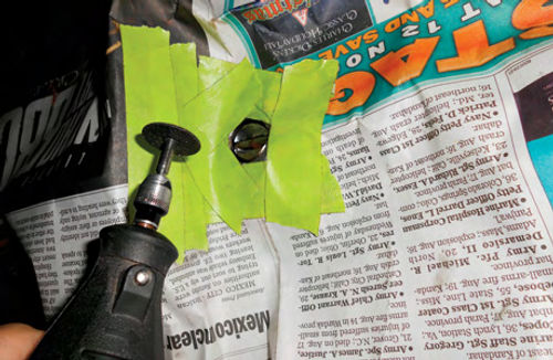
Before starting this task, great care must be taken to make certain that no abrasive dust enters the differential. A section of newspaper was used and a circle with a diameter of 1 1 ⁄2” was cut out in the center.
Next the area of the case surrounding the pinion shaft was cleaned with lacquer thinner, and the cutout in the newspaper was centered over it and taped down. The differential housing as well as the area around the pinion shaft was now sealed, so the abrasive dust from the cutting wheel would be kept out.
A small reinforced cutoff wheel (part #426) was used with the Dremel to get started. Avoid using the non-reinforced wheels, they have a tendency to explode and go everywhere. The abrasive wheel that was already mounted on the arbor had been used a few times, so the diameter was smaller than a new one. This was actually an advantage in this situation.
The wheel was worked back and forth carefully; there is very little travel involved, as you want to avoid contacting the case. Photo 4 shows the process. Probably 90% or more of the metal removal was accomplished with the cutoff wheel, but the edges were worked with a small grinding stone. Grinding through the end of the hardened pin didn’t take as long as expected, but performing this task while lying on a creeper is sure tough on your neck.
Once the metal removal was completed, the pick tool was used to try and push the broken bolt out as seen in Photo 5. Once again it would rotate freely, but would only slide a little bit, and then bind up.
Maybe a little more “punch” would do it. In Photo 6 a drill is being used to make a small dimple in the broken bolt. This would give the pick tool an edge to drive against. In Photo 7 a small hammer is used to tap the heavier pick tool. Unfortunately, it’s impossible to obtain the desired angle with the pick because the ring gear gets in the way. However, it can still be driven in the proper direction, just without as much force. A more in-line approach with the broken bolt would have been more effective.
Still, the broken remnant finally started to advance slightly. The pin was rotated a bit and another dimple was drilled into it. The same procedure was repeated, and finally some real movement was obtained.
All of a sudden it was free, and almost went flying out of its hole. The end of the bolt was found to have a slight ridge on it. This is possibly the reason it would move a little, and then get stuck. This ridge was likely getting hung up in the bottom of the case (left side).
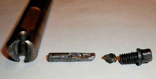
Photo 8 shows the sacrificed pinion shaft and the three pieces of broken bolt. A thread chaser was used to clean out any junk created during the epoxy attempt that might have remained in the threads of the case.
An interesting note: The new pinion shaft pin purchased from Chevrolet had a clearance hole for the bolt that was .040” larger than the original one. There certainly must have been a reason for this change, and possibly it’s related to bolt breakage issues.
I couldn’t help but think how difficult it would have been to explain this situation to a “customer” in a repair shop environment. Thankfully, I don’t have to do that.


