Installing a Disc/Drum Brake System
Join In As This Pickup Truck Owner Switches Over From a Drum/ Drum Setup. Car Owners Take Note: You Won’t Have To Cut an Access Hole.
ONE DAY I may stop upgrading (tinkering with) my truck but having front disc brakes seemed so logical I just couldn’t pass it up.
I got a basic disc brake kit, without master cylinder upgrade, from a national classic vehicle vendor for about $450. I bought a standard disc/drum master cylinder and an adjustable proportioning valve for about $120 from my favorite parts store and made an adapter bracket to install the master cylinder.
This project follows a logical progression; modifying the drum brake system, installing the adapter and rotor assembly to the spindle, re-connecting the brake hoses from the new calipers to the vehicle, upgrading the master cylinder, replacing the single brake line with two brake lines, installing a proportioning valve and modifying the driver’s side cab floor for access.
So let’s get started.
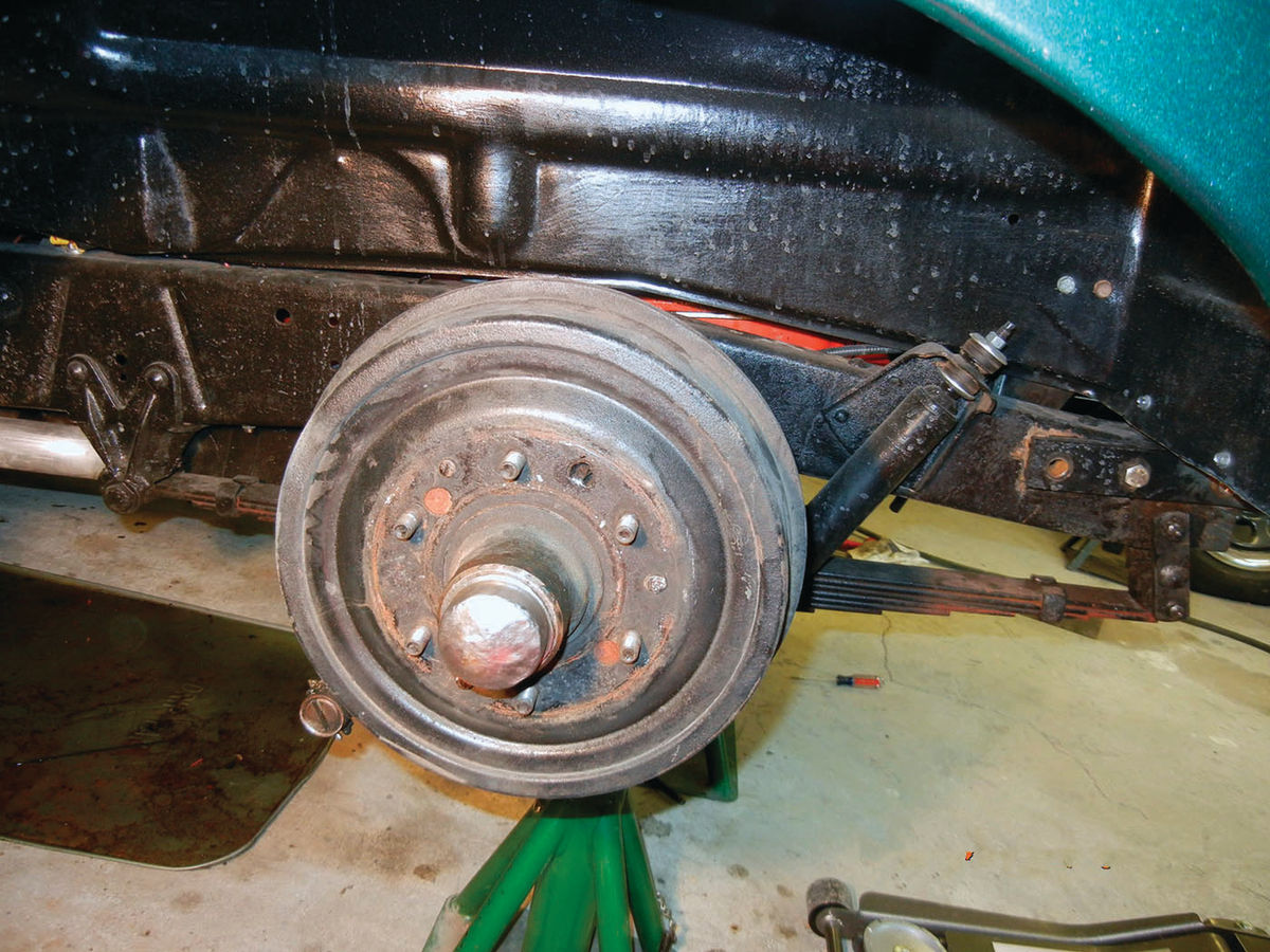
Modifying the Existing Drum Brake System (Photo A)
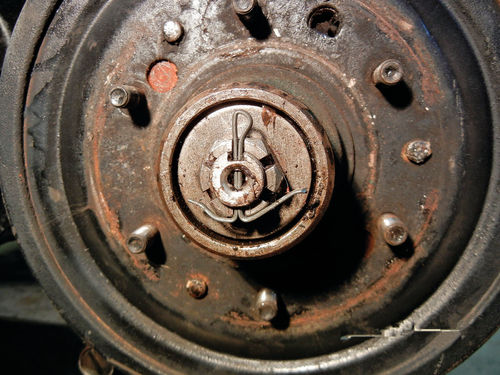
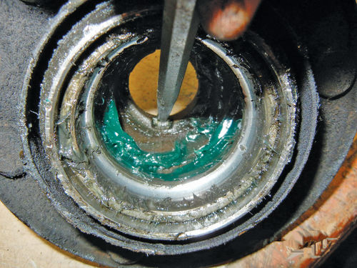
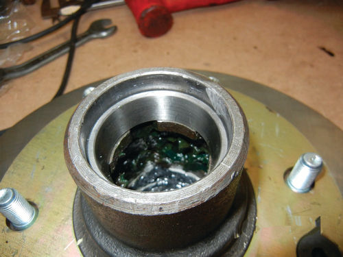
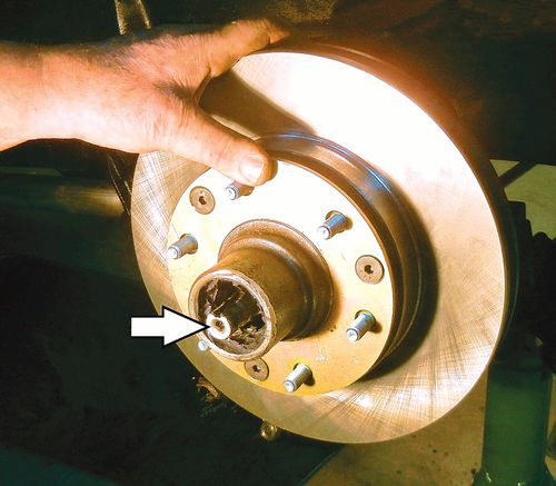
Remove the spindle cap to reveal the cotter key and castle nut that secures the brake assembly to the spindle (Photo B). You will find a bearing set behind the castle nut and indexed washer. Set these aside for possible future use.
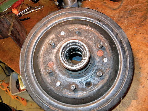
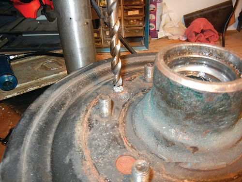
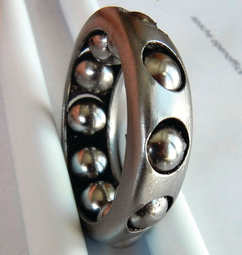
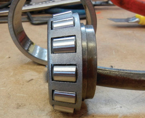
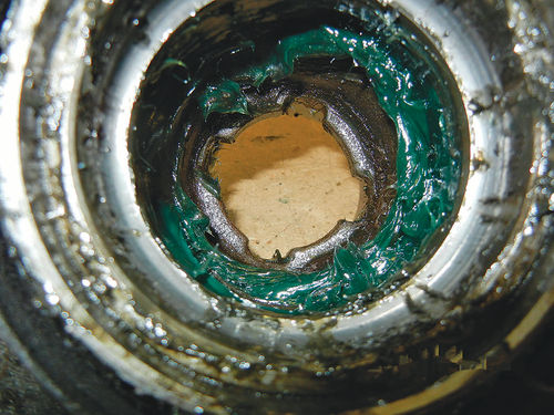
The brake drum is held to the hub by three rivets (Photo 1). Release the hub from the drum by drilling out three rivets with a 3 ⁄8" drill (Photo 2). The hub contains two round bearings, one on each side, that were removed when we took the hub off the spindle (Photo 3). The races for the bearings are pressure fitted into the hub. Both races need to be removed IF YOU CHOOSE TO REPLACE the original bearings (Photo 4) with more modern tapered bearings (Photo 5).
If the bearings in the hub worked very well when you took the brake drum off the truck, they may simply be re-installed; or you can upgrade to more modern tapered bearings developed to compliment the newer disc brake system. I chose the new bearings because they offer more bearing surface to support the newer disc brake system. The original bearing races are removed using a punch and hammer (Photo 6). Tap them out, moving the punch around the outside in the slots, spaced 90 degrees apart, provided in the hub (Photo 7). Once the original bearing races are removed, install the new races by tapping them into the hub. The races go into the hub below its surface. Use a punch to tap them all the way down until they bottom out (Photo 8).
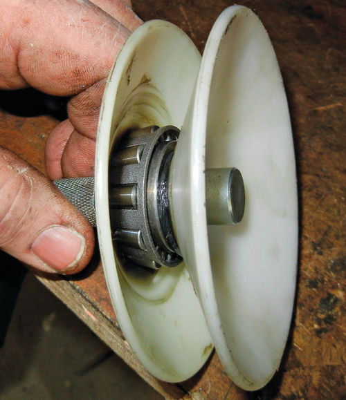
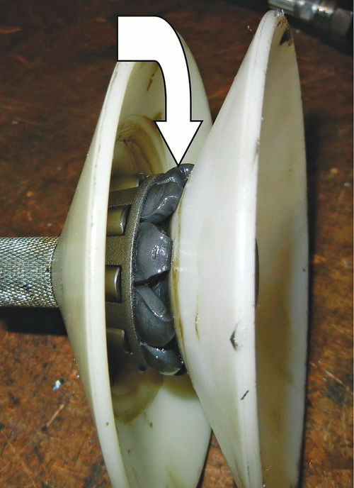
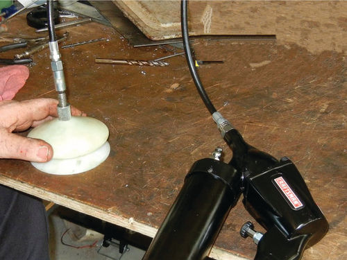
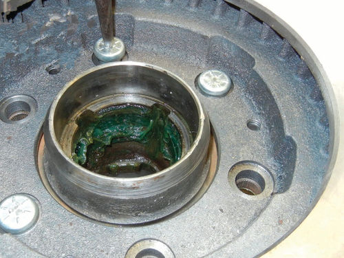
The new bearings need to be thoroughly lubricated before they are ready for installation. You can do that by hand or with a lubrication tool designed for the work. Photo 9 shows the bearing installed in the tool and Photo 10 shows the bearing with the grease installed. The bearings must have lubrication inside the entire bearing housing. I used an air-pressure operated grease gun to insert the grease (Photo 11).
With the hub preparation complete, follow the instructions to connect the rotor to the hub. In our case the kit included a 3 ⁄8"-thick spacer. Install the new wheel studs (Photo 12).

Installing the Disc Brake System
There are numerous kits available online. Some of the components are available from your local parts store but getting everything you need to match your vehicle is difficult and I am not aware of a source for the necessary spindle adapter plates.
A non-power assist dual reservoir master cylinder is available online and at your local parts store.
Install the adapter plate to the spindle, per the manufacturer’s instructions, using the holes in the spindle (Photo 13). The two holes at the top of the spindle may be different in size than the lower two holes. My kit included the different-sized bolts needed to complete the installation.
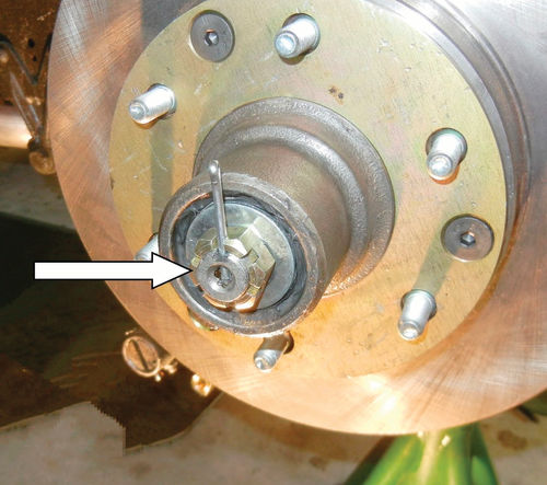
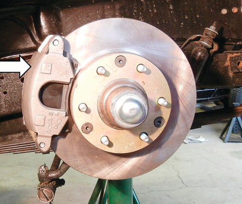
Install the assembled rotor assembly (hub, inner [larger] bearing with seal, and rotor with wheel studs) onto the spindle (Photo 14). Install the outer bearing, washer with indexing tab, castle nut, cotter key and dust cap. The castle nut is tightened to about 12 foot-pounds of torque while rotating the rotor. When it’s tight enough, slowly loosen the castle nut. Line up the previous notch in the castle nut with the hole in the end of the spindle. Insert the cotter key into the spindle and through the castle nut. Install the cap (Photo 15). Install the brake caliper over the rotor and secure it to the adapter plate (Photo 16).
Brake Hose Attachment
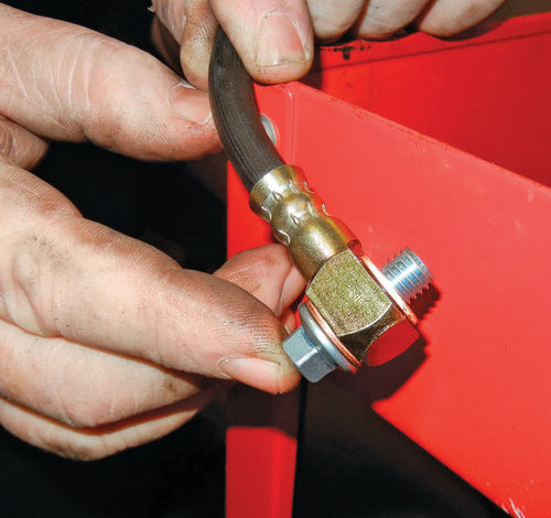
The new disc brake assembly is connected to the truck’s hydraulic brake system with a flexible hose that uses unique attaching components on each end.
One end of the hose attaches to the caliper using a bolt that passes through the side of the hose. This bolt secures two COPPER washers, one on each side of the hose end, that seal the connection to the caliper (Photo 17). Without these “soft” washers and machined hose end, the connection would leak brake fluid.
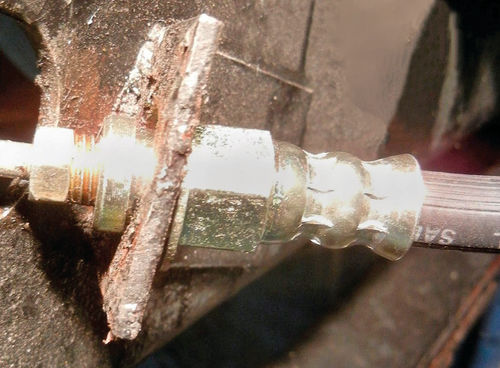
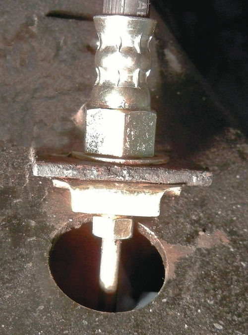
The other end of the hose connects to the frame of the vehicle and the metal lines going back to the hydraulic master cylinder. This hose end freely passes through a hole in a metal bracket; the end of the metal brake line screws into the end of the hose (Photo 18). The connected line is pinned to the bracket with a brass clip inserted into a slot in the end of the hose (Photo 19).
The Master cylinder Upgrade
The stock brake system on my truck used a master cylinder with one fluid reservoir (Photo 20). As long as the hydraulic system was well maintained and the metal brake lines not damaged, the system worked well.

More recent master cylinders are made with two reservoirs, each reservoir providing pressure to either both front wheels or both rear wheels. If, during operation, a brake line leaks or fails, the other brake line could be available to stop the vehicle.
I bought a dual reservoir master cylinder from my local parts store, designed for a ’71-’72 Chevy C-10 pickup truck (Photo 21). They also are available online. This master cylinder is NOT part of a power-brakes system; it was designed to operate manually on a braking system with front disc brakes and rear drum brakes. Note that the two brass brake line connectors are NOT the same size. (The system schematic is available online. Google “1971 Chevrolet truck brake system.”)
On my truck, the mechanical components that attach to the brake pedal and clutch pedal are bolted onto a metal platform that is bolted to the vehicle’s metal frame. There are four bolts that attach, through the frame, to the platform and one pivot bolt with a 15⁄16" nut, which also attaches through the frame. This platform provides the surface to attach the master cylinder, brake pedal and clutch pedal to the frame (Photo 22). The large bolt provides the pivot point for the pedals to push on rods connected to the master cylinder and the manual transmission.
You do not have to remove the bolted-on metal platform. You may just remove the original, single-reservoir master cylinder by undoing two bolts and the connecting rod.
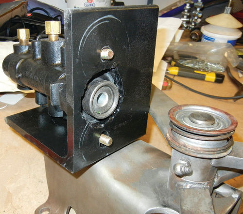
The pictured master cylinder is attached to the vehicle using an adapter/ bracket. This adapter/bracket is also available online or you can make your own. I got the steel from a local vendor and had him punch the 2" hole through one side. (We dropped and broke the tip on my friend’s plasma cutter trying to cut the hole ourselves.)
The adapter/bracket attaches to the metal platform and the master cylinder attaches to the bracket. Once I was sure it would all work I installed the components onto the metal platform one piece at a time.
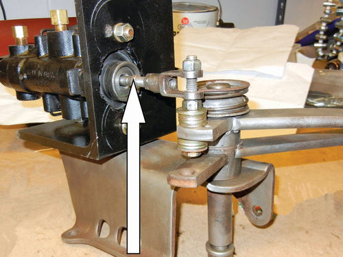
The connecting rod from the brake lever to the old master cylinder needs to be relocated to line up with the new master cylinder. CAUTION: The master cylinder must be of a type that accepts the connecting rod inside the body of the new master cylinder; the connecting rod must not sit on the outer surface of the master cylinder (Photo 23). The rod is held in place at the brake lever with a pin and cotter key, the opposite end is held in place by being inside the master cylinder.
Be sure to slide the rubber boot over the connecting rod before installation. (I didn’t the first time.)
New Brake Lines
With the new master cylinder in position, replace the existing single brake line with two brake lines; one line to the front brakes and one line to the rear brakes.
The first question is, which master cylinder reservoir serves the disc brake portion of the system and which one services the drum brake portion of the system?

Drum brake master cylinders have a “residual pressure valve,” a check valve that keeps the brake shoes close to the drum so there is little or no brake pedal travel before the brakes respond.
Disc brake master cylinders do not use a check valve because if they did the brake pads would drag on the rotor.
The solution, for a disc/drum system, is to have one reservoir discharging directly into the brake line without a “check valve” and the other reservoir discharging into the other brake line with a “check valve.”
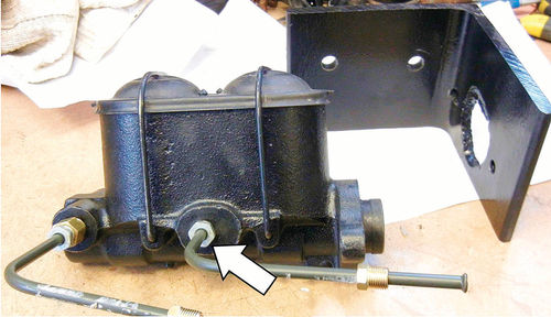
In our case the front reservoir in our master cylinder discharges directly into the brake line. (The arrow in Photo 24 points to the FRONT reservoir discharge connector to the brake line.) The rear reservoir discharges out of a larger port in the side of the master cylinder. This port was made larger by the manufacturer to install a check valve into the master cylinder. The rear reservoir discharges through a check valve and then into the brake line.
The front reservoir’s brake line, the one closest to the engine, goes to the front disc brakes and the rear reservoir’s brake line goes to the rear drum brakes.
Brake lines come in multiple diameters, are sold in various lengths, may come prefabricated with a double flared connection on each end, are flexible enough to be bent with a number of specialty tools and are available at most parts stores. Cutting the lines to the necessary length, and then restoring the double flare to the end of the cut brake line, requires a “Double Flaring” tool kit. The kit is designed to work on the thin wall steel tubing normally used for brake lines, and most kits will also work on aluminum or 0.40 soft-wall copper.
I found a well-presented tutorial online at: http://theymightberacing.com/Shop Tech/FuelBrakeLineFabrication.aspx that you might find helpful.
For those who have not done this before; use the brake line you took off the vehicle, cut off an end, then restore the double flare per the instructions in the kit. Practice 4-5 times until you’re comfortable doing it. Expect the results to be unacceptable on a few of those practice efforts and even possibly on an attempt with the brake line you intend to install.
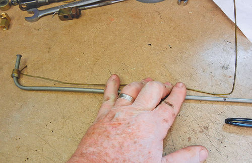
The second question is; how long should the new line be and where should I bend it?
One way is to use a welding rod, a stiff coat hanger, etc., to lay out a pattern by hand on the vehicle where you want the new line to run. Then go to the bench to duplicate the bends and turns on your new brake line using the pattern (Photo 25).
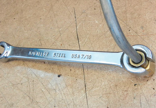
Brake line connectors are frequently made of brass or aluminum; softer metals than steel. Standard wrenches may be used to connect the brake line system together, but there is a better way. Use a wrench designed to slide over the brake line but wrap around the bolt (Photo 26).
About That Adjustable Proportioning Valve
An adjustable proportioning valve allows you to balance the brake fluid pressure between the front and rear brakes for smooth safe stops. Disc brakes require considerably more pressure to operate than drum brakes, so disc/drum combination systems frequently require the use of an adjustable proportioning valve. Without a properly adjusted proportioning valve, the drum brakes may lock up before the discs do, which could result in handling and safety problems.
The proportioning valve is inserted into the brake line serving the rear drum brakes at any convenient location after the master cylinder and before the brake line branches off to both rear wheel cylinders.
Access to the New Master Cylinder
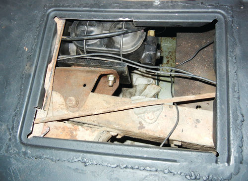
The 3" diameter hole in the floorboard of my truck didn’t provide the access needed to take the top off the new master cylinder. I could have cut a hole in the floor, fashioned a larger access plate and screwed it down with metal screws. Instead I used the battery door system from the passenger side of a donor truck (Photo 27).
I like the results of my brake system upgrade and hope your efforts go well for you.


