Diagnosing and Repairing a Rough-Running Engine, Pt. 3
The Engine’s Running Well With the Points Distributor We Installed Last Month, But It Should Be Even Better With an Electronic Ignition Kit. We’ll Also Repair the Engine’s Original Distributor.
Editor’s note: For the past two months we have followed the diagnosis and repair of a rough-running condition on our project ’55 Chevrolet, and we finally have a car that is running well. We started by assessing the engine condition, performed a basic tune-up, fixed an intake manifold coolant leak, rebuilt the carburetor and replaced a faulty electronic distributor with a stock points distributor. Overall engine performance has been substantially improved, and the car finally is in good running condition.
The final step in this long journey will be to install a new electronic ignition module in place of points in the stock distributor. Follow along while we install a Pertronix Ignitor 3 electronic ignition kit into the stock distributor. We will also tear down the faulty aftermarket distributor that we removed last month and repair it for a future project. Last month we showed Photos 7 through 11. We’ll start this month with Photo 12.
The Pros and Cons of an Electronic Ignition
Points distributors have been around a long time, are quite reliable, and easy to fix. They also tend to degrade slowly over time, rather than to just fail outright. So, after all the issues we have worked through on this engine, why would we go back in and tinker with what is now a working combination? In other words, why mess with a good thing? Good question, especially since I am already pretty happy with how well the car is running.
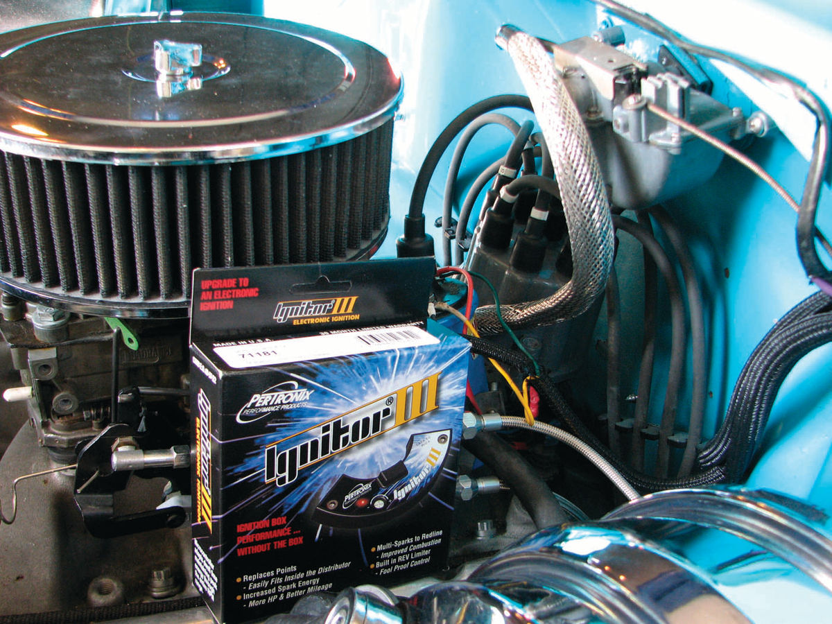
Actually, I thought long and hard before deciding to go ahead with installing the Pertronix Ignitor 3 system. The advantages of electronic ignition are easier starting, increased gas mileage and improved performance. Also, no more points to change or adjust during tuneups. The Ignitor 3 adds the benefit of a user-adjustable rev limiter and multiple sparks for each ignition cycle. These add up to an engine that should run a little more efficiently and more cleanly.
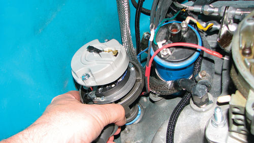
Appearance-wise, from the outside the distributor looks stock, other than having two wires hooked up to the coil instead of just one.
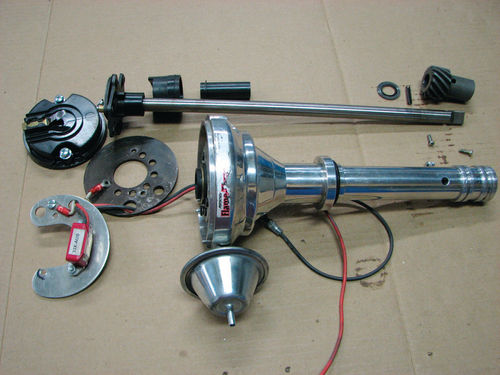
I have also used this brand of electronic ignition in the past with good success on other projects. And, if necessary, reverting back to points is pretty easy and inexpensive in the event I ever need or want to go that route (Photo 12).
Starting From a Known Good Baseline
In light of the long history of rough-running problems this engine has had, the last thing I wanted to do was to introduce more changes until I knew for sure we had a good, solid running and driving engine. Otherwise, if there were problems we wouldn’t know if they were from the conversion or an old problem that had resurfaced. I ordered the parts I needed from my favorite retailer. While I was waiting for the parts to arrive, I drove the car every day for two weeks, exercising it under many different conditions—lowspeed city driving, highway cruising, stopand-go traffic, and hot idling conditions. By the time the parts arrived, I was very confident that we had a good-running engine to build on.
Let’s Move to the Bench
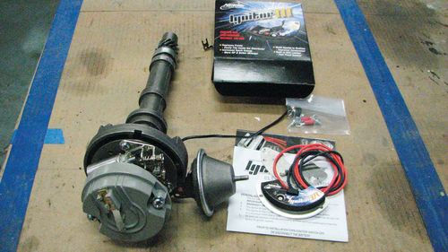
The new distributor module can be installed with the distributor in or out of the car, but my strong preference was to pull the distributor and install the module on the bench. It is much easier to do the work that way, especially on a small block Chevrolet where the distributor is in the back of the engine by the firewall. Removing and installing the distributor is actually a pretty quick job, as long as you are mindful to mark down the direction the rotor and distributor housing are pointing so it can be reinstalled in the exact same orientation. For people who are not comfortable removing the distributor, all the work can be done in place, it just requires a fair amount of reaching over the fenders. The actual installation procedure is the same (Photo 13).
Out With the Old
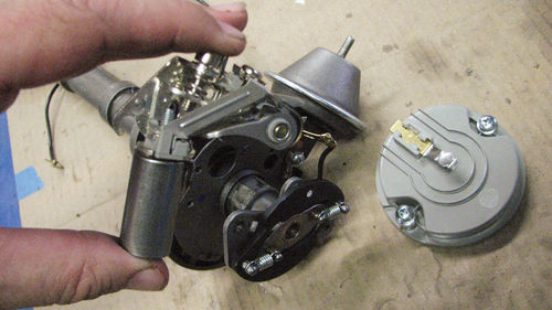
The first step is to remove the old parts. With the distributor on the bench, I started by removing the rotor to make it easier to see, and then removed the old points and condenser, which I saved for my emergency roadside tool kit (Photo 14). Then I removed the wire and old grommet for the points wire that runs to the distributor. Since this distributor was freshly rebuilt, the work was clean and easy. If it had been a used distributor, I would have taken some extra time to clean the housing and to check the bushings to make sure the distributor wasn’t excessively worn and that the vacuum advance was working properly.
Installing the Pertronix Module
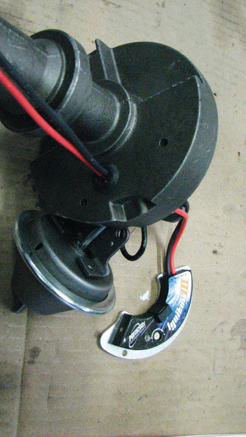
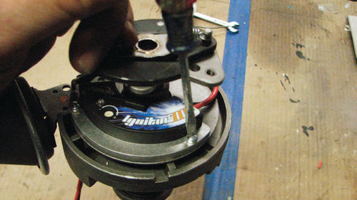
First, a new grommet was installed into the distributor housing, and then the two wires were routed from the Pertronix module through the new grommet. This is done before installing the adaptor plate, when it is easy to access and properly route the wires through the base of the distributor. Performing this work on the bench allows the distributor to be turned upside down to insert the grommet. If you are doing the installation on the car, take care to make sure the grommet is fully seated in the hole and the wires are routed through the hole in such a way that they can’t chafe (Photo 15).
Next, an adaptor plate was installed and screwed down where the points and rotor used to be mounted. The electronics module will mount on this adaptor plate. The screws are carefully started, then tightened down. Finally, the Pertronix module is installed to the adaptor plate, then the distributor is ready to reinstall (Photo 16).
The new ignition module has a builtin rev limiter function, which is set via a screwdriver setting on the module. The default setting is appropriate for this stock engine. If I wanted to change the setting, the instructions are pretty thorough, and an LED light on the module provides feedback that the rev limiter is set to the desired rpm.
The distributor was reinstalled into the engine. Notice that I used a fresh base gasket to prevent oil leaks. A torn distributor gasket won’t leak much, if any, at idle in the garage, but can create a moderate oil leak on a road-driven car. I was careful to align the rotor so that it pointed to the same angle as when it was removed, and engaged the oil pump drive shaft. After the distributor was fully seated, I rotated the outer housing to the same orientation as when I removed it. The distributor clamp was reinstalled and I tightened it to snug, but left it loose enough that I could turn the distributor for final timing adjustments. This set the timing close enough to allow the engine to start (Photo 17).
Setting the Ignition Timing
With the distributor reinstalled, the timing light was connected. The engine started fairly easily, and then I adjusted the timing “by ear” and allowed the engine several minutes to warm up before making any final timing adjustments.
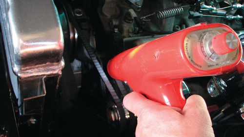
Once the engine was warmed up to operating temperature, the choke was fully open, and the carburetor was at a normal idle (the fast idle cam was fully off), I made the final timing adjustments. I disconnected and plugged the vacuum advance line from the distributor. Using my timing light, I adjusted the ignition timing to 8 degrees before Top Dead Center, which is a good setting for this engine. Once the timing was set, the distributor clamp was tightened down and the vacuum line reattached. At this point, everything was done and ready for the road (Photo 18).
Road Test Results
Initial observations have been favorable. The engine does indeed start well, although in fairness it did start fairly easily with a fresh points ignition. Overall engine performance is definitely improved at high rpm and at full power. Cruising performance around town seems about the same, perhaps slightly better. I have not had a chance to measure the economy improvements yet, since I have not taken any road trips but informally it does seem improved. It will take some time to know if there is a measurable mileage increase, but I suspect there is.
One interesting and unusual thing I discovered is that the multi-spark function causes my timing light to be confused at all settings except at “0 degrees.” I use a Snap On timing light which has a built-in timing degree function which allows the user to turn a dial to the desired timing value, then set the timing so the marks line up at top dead center. In the past I have found the timing function on the light to be very handy to dial in the idle timing and total timing values at idle and high rpm on performance engines. Unfortunately, the multi-spark function appears to cause the timing angle function in the light to misbehave. Setting the adjustment to “zero” disables the timing degree function and allows the light to work properly.
Rehabilitating the Old Distributor
With the new distributor dialed in, it’s time to return our attention to the old points unit. I wanted to find the cause of the misfire in the first place, and see if the distributor could be brought back into good working order. I started by removing the distributor drive gear from the shaft. It is held in place by a roll pin, which was gently tapped out using a driver punch and a hammer. A block of wood was used to support the gear so that the force from the tapping didn’t go into the distributor housing or bushings (Photo 19).
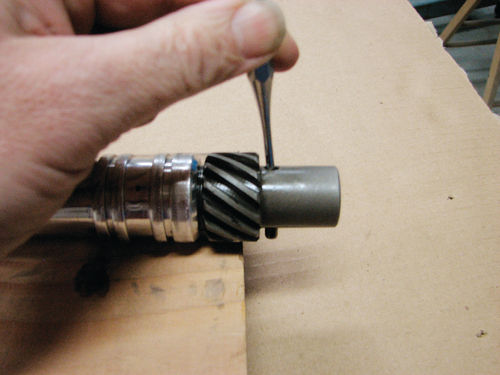
With the drive gear and spacer shims removed, the distributor shaft assembly was pulled up and out of the housing. The mechanical advance mechanism was disassembled and removed, and the distributor was disassembled to its smallest components. Everything was carefully cleaned, inspected and measured as necessary (Photo 20).
Surprisingly, everything checked out good and cleaned up nicely. The aftermarket distributor uses a roller bearing at the top, so the shaft fit tightly. There was a bit of side-to-side looseness in the mechanical advance mechanism (the magnet wheel is attached to it), but cleaning up the mechanism, removing a few burrs to allow the parts to seat better, and properly shimming the distributor shaft tightened things up.

The big problem was the excessive gap between the sensor and the magnet wheel. There is no adjustment for this measurement, but by carefully slotting the screw holes on the mounting plate I was able to move the entire assembly closer. The initial gap was over .080 (measured with a round feeler gauge), but by slotting the screw holes I was able to close the gap to .050, which is well within the specification limits without running the risk of interference (Photo 21).
I am currently using this distributor on a newly rebuilt engine I have on a stand in the workshop, and it is working great. I’m very confident that the fix has returned this distributor to good working order. I will probably use this on the street in a future project car, but if I do I probably will replace the electronic module just to be on the safe side.
Resource
Pertronix Performance Products
Corporate Office
440East Arrow Highway, San Dimas, CA 91773


