
Building Some Homemade Exhaust Cutouts
It Took a Few Tries to Get It Right, But Now He Can Cruise Legally and Still Hear Some Serious Exhaust With a Hard Push of His Right Foot.
I have an addiction. But it’s not a problem for me, only for my neighbors.
It has to do with a 1965 Corvette I have owned for 37 years. During that time I have had the engine and transmission out several times. It originally came with the 300-horsepower 327, but I have since replaced that engine with a 350 that was stroked to 383 cubic inches. Here’s where we get to my addiction. During the engine transition periods there have been times when I’ve had the chance to drive my Corvette around with open headers.
Very few things, and I have to be careful how I say this because my wife will probably proofread the article, bring a smile to my face quicker than the roar upon startup and acceleration of an open-header V-8.
Trying On Some Purchased Cutouts
A few months back I decided to look into putting some commercially available exhaust cutouts on the car. So I bought a set of electronically controlled cutouts from Doug’s Headers.
However, I had trouble with these immediately as they sometimes would not open when hot. I sent one pair back and received another set. These worked better but still not 100% of the time. I am suspicious of the small-gauge wiring harness that was supplied with the cutouts. It probably was 18- or 20-gauge wire. I made a 14-gauge jumper cable and got them to work more consistently. But I still wasn’t 100% convinced that the heavier wire would solve the problem, so rather than spend the time it would take to rewire the car, I decided to make my own cutouts.
The First Try Didn’t Work
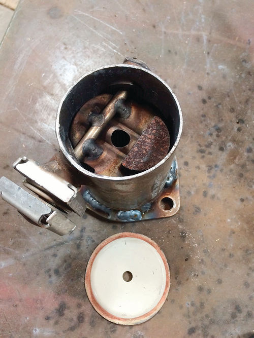
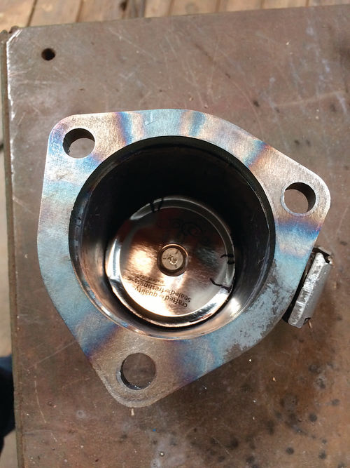
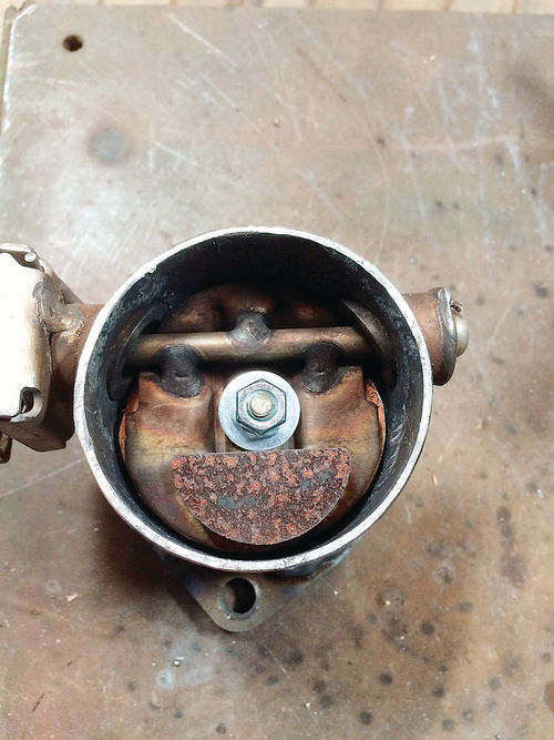
My first attempt at homemade cutouts started by finding a Chevrolet butterfly valve found in late-model V-8 pickups. I can only speculate what this valve does in the exhaust system. Perhaps it increases the backpressure when the engine goes into 4-cylinder mode. It was a simple process to weld these valves onto a standard flange ring. The valves do not completely seal the exhaust because of the hole in the middle and some clearance along the edge. Maybe 80% of the outlet was blocked.
Once installed on the car, they were a little quieter than open headers but not street legal. I then bolted the lid of a jam jar onto the existing flap and maybe got a 95% seal. Now the car was a little quieter but still not street legal when just cruising around.
For a while, I set the project aside.
Let’s Try a MoreElaborate Design
Some time afterward I was discussing this problem with my mechanic friend, Kurt Mathewson. He came up with an adjustable spring-tension flapper design that became my second attempt.
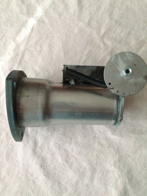
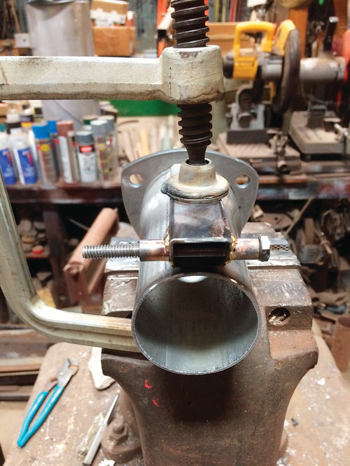
I started with some 2.5-inch pipe that I had my muffler shop flare to fit the 3-inch flange ring. I did make a mistake here as the original Y pipe from Doug’s Headers is closer to 2 5/8 inches ID. But believe it or not, if you use 1/4-inch bolts instead of 3/8, you can mount a 3-inch flange to the smaller outlet. This wasn’t ideal but it worked well enough to let me finish the development. Once I came up with the final design, I made another set that correctly fit the outlet on the Y pipe.
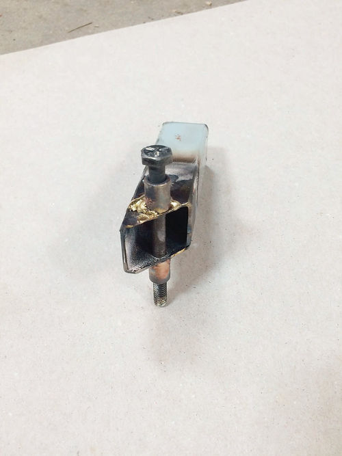
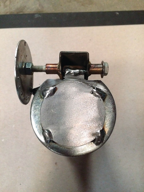
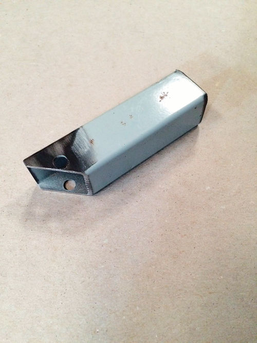
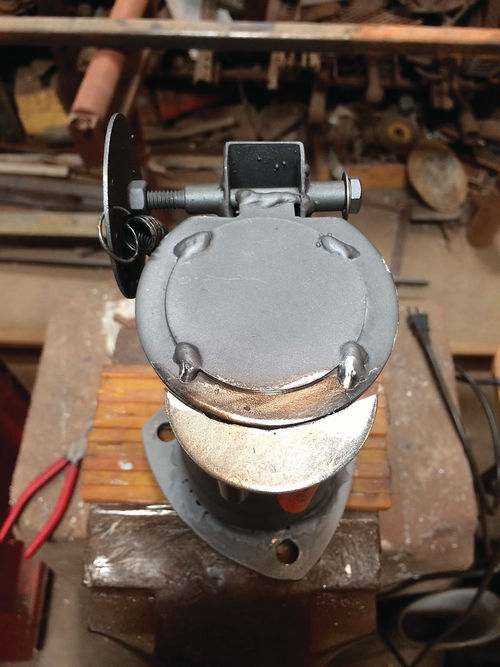
Next I angle cut some 1-inch square tubing and drilled a 1/4-inch hole for the rotation shaft, which is a 1/4 x 3-inch bolt. I placed a 3/8-inch OD x 1/4-inch ID brass bushing on the bolt and put it through the two holes in the square tubing. I then brazed the bushing in place to act as a bearing. I flipped the tubing around and did the same thing to the other side. By placing the angled tubing on the pipe, I could position the shaft so that I could weld the flapper to it. This was simply a 3-inch washer. I tend to use parts I have available in the shop. I knew I could patch the washer hole later. I then notched the washer so that a 3/4-inch tab could be welded to the shaft and have clearance as the flapper opened.
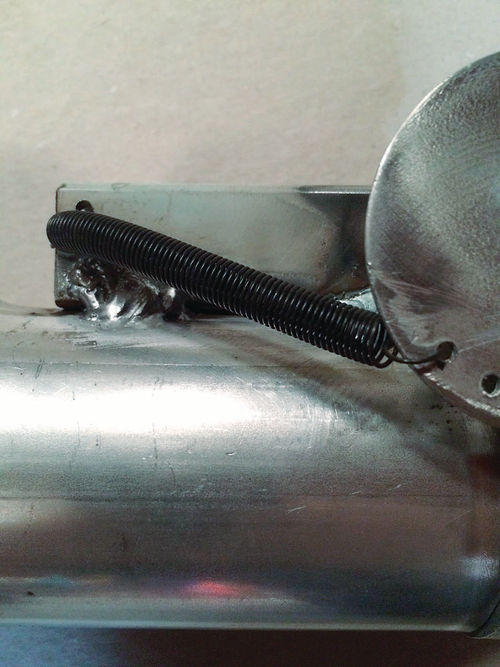
Next I drilled some spring adjustment holes in a 2.5-inch flat steel patch that
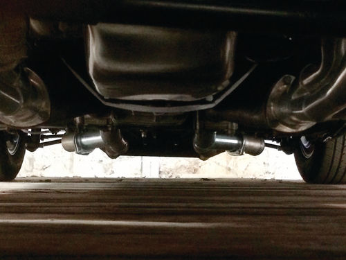
I found at the muffler shop. I drilled a small hole in the square tubing and now had two attachment points for the spring. I hooked the spring up and then mounted both units on the car.
Some Magnets to the Rescue
Upon startup, I could hear that this approach was not working either. At idle and beyond they rattled with the engine pulses. The resistance through the mufflers was forcing the air through the flapper valve.
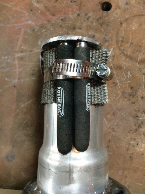
I put a heavier spring in and still had the problem. Kurt suggested that I add a tab on the end of the flapper and place a magnet in position to keep them more secure at slow speeds. I robbed a magnet from my magnetic pickup tool. I wrapped the cutout in header wrap and used a hose clamp to keep the magnet in place. Everything went together securely but it turned out one magnet was not enough.
I made a run into Orchard Supply Hardware and bought several different kinds of magnets, including three more similar magnetic pickup tools. I then added the tab to the bottom of the flapper valve and secured two magnets with the setup described earlier.
Upon startup, things were quiet, but would the cutouts open up under wideopen throttle? The three tool magnets I bought were made by General Tools, part number 394, and were individually rated to pull 5 lbs. So each valve had 10 lbs. of pull to overcome. A test run showed that they seemed to open up when the carburetor secondary’s opened. Perfect. One side opened up slightly sooner than the other, probably because my first pickup tool magnet was slightly weaker than thethree new ones (General Tools & Instruments, generaltools.com).

Kurthas also suggested that I move the square tubing spring attachment point a little farther away from the pipe so that the heat would not impact the spring’s temper.
In addition to my thanks to Kurt for helping me work my way through this project, I’d like to offer a special thanks to Dave Thurber who attached three Go Pro cameras to the car, two on the flapper valves and one on the tachometer. This helped us dial everything in (gopro.com).


