
Building a 427-Cubic-Inch V-8
They Bought an Engine and Then Found the Perfect Car for It. So It Was Time to Launch a Rebuild Project.
IT’S A RARE thing to start with an engine and then have to find the car to fit it. But that’s what happened eight years ago when we went on our first Jeep rock crawling trip. For the more extreme rock crawlers, horsepower was the order of the day. But having a high-horsepower 427 cid engine and knowing how to keep it running seemed to create a quandary for our friend.
We got it running for him for the weekend but then our friend proclaimed he was going to swap out his power plant for a crate 454 big block. At that point, we jumped at the chance and bought the 427. We didn’t know what we were going to do with it, but all the same we had a 427 big block.
A Camaro Appears
Fast forward eight years and the family had finished a myriad of classic Chevy muscle car restorations. We had a 1967 Chevelle SS with a 454, a 1967 Chevelle convertible with a 454 and a 1969 Chevelle with a 454. It would only stand to reason that the family would be on the hunt for a 1969 Camaro to wrap around that 427 we had purchased so long ago.
After a few possible prospects failed to materialize, a friend called from the Moultrie, Georgia, Classic Car Show and Swap Meet and proclaimed, “I found you a Camaro. It looks good but no engine or transmission. Bring cash and a trailer and it’s yours.” You didn’t have to tell us twice. We hooked up the car trailer, collected the cash from the bank, headed up the road and made the purchase.
Now that we had a car for our 427 big block, it was time to break down the engine and rebuild it for our newly acquired Camaro.
Our Approach to Building a Chevrolet 427 V-8
There are as many different methods for assembling a Chevrolet big block as there are engine assemblers. Everyone has their different habits and quirks; this is just our way:
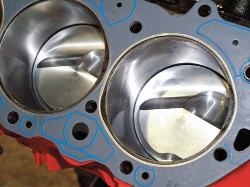
After the engine has been disassembled, check the cylinder walls for scratches or imperfections. This engine had damage to the number six cylinder which required a trip to the machine shop. The engine previously had been bored to 0.060" oversized (sixty thousandths) but with a scratched-up cylinder wall we had to bore even larger. So this engine was bored to 0.100" oversized (one hundred thousandths). The crankshaft then was ground and polished for new bearings.
With the block machine work complete and all parts available, assembly of the engine could now commence.
Our Parts List
• Keith Black pistons and rings
• GM High Performance full-floating connecting rods
• Hastings connecting rod and main bearings
• Howard roller camshaft
• Rectangular port L88 aluminum heads
• Wieland intake manifold
• Fluid dampening harmonic balancer

Step 1
Attaching pistons to connecting rods.
Tools needed — bench vise, small jewelry flathead screwdriver, small needle nose pliers.
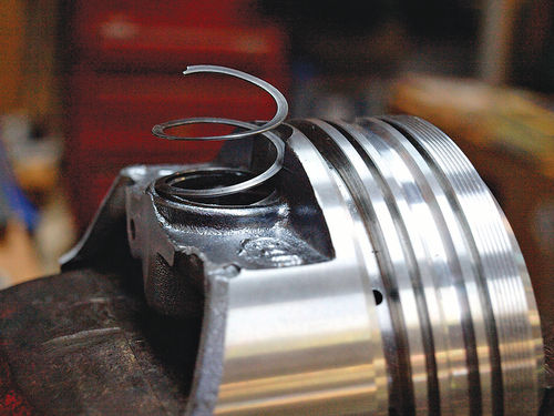
To connect full-floating wrist pins, it is necessary to use a lock ring. Our preference for this project was a spiral lock ring.
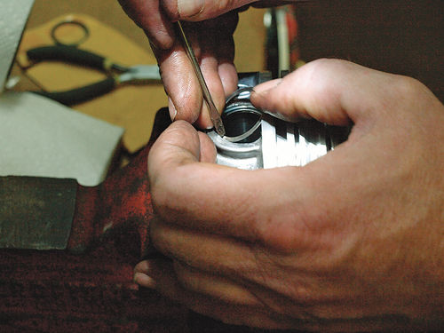
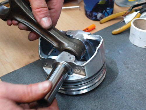
Carefully place a piston into the vise with the wrist pin hole directed up, clamp down (Photo 1). Un-spring (only slightly) the spiral lock ring (Photo 2). Using the small screwdriver, start pressing one end of the lock spring into the groove for the lock ring (Photo 3). Work your way around the opening until all the spiral ring is snapped into place. Insert the wrist pin; slide the connecting rod onto the wrist pin (Photo 4). Return the piston to the bench vise with the opposite side of the wrist pin hole facing up. Insert a spiral lock ring as previously instructed. Repeat seven more times.
Step 2
Placing Piston Rings on Pistons.
Most piston manufacturers supply rings for their pistons. They’ll also give you an instruction sheet that will tell you how to properly install their piston rings. Make sure you read that instruction sheet.
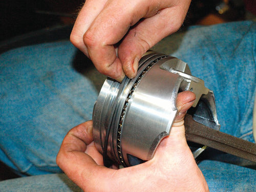
For these piston rings, the instructions state “dot to the top.” That is, the dot on the top of the ring should be pointed to the top of the piston. First, slide the oil control ring down the piston to the groove closest to the piston base (Photo 5). Do this carefully so as not to damage the sides of the piston. Consider using your thumbs on each edge of the ring to slightly spread the ring open. Then add the 2nd ring (double-check the instructions for the direction of this ring), then add the top ring.
Step 3
Installing the Crankshaft.
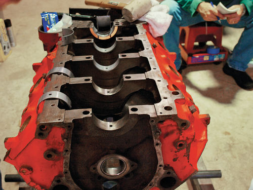
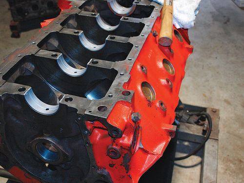
If you’ve not already done this, it’s time to position your block on the engine stand with the bottom side facing up (Photo 6). The back of the engine should be the attachment point to the engine stand.
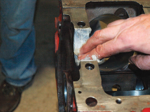
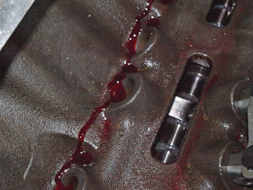
Crankshaft bearings come in two halves; one of them has an oil hole. Place the bearing with the oil hole into the block. The block surface area for the crankshaft bearings should be clean. Once all of the crankshaft bearing halves are in place (Photo 7), lubricate the halves with petroleum jelly (Photo 8).
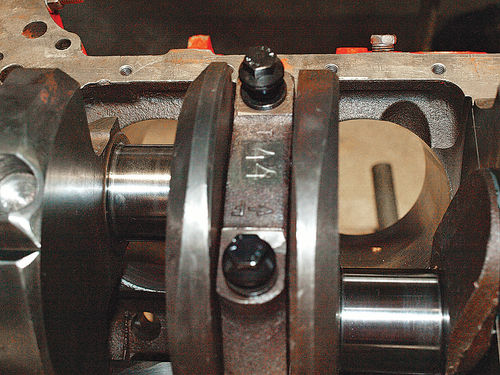
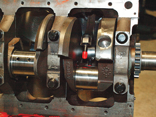
Place the crankshaft into the block uniformly from front to back with no tilting of the component (Photo 9). Once the crankshaft is in, place the other halves of the crankshaft bearings into the main bearing caps. Once the bearings are in the caps, lubricate with petroleum jelly and install the main bearing caps. Bearing caps are numbered with arrows pointing toward the front of the engine (Photo 10). Ensure that the caps are in order and pointing to the front of the block.
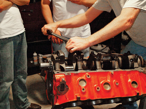
Hand-tighten the main bearing cap bolts and then set your torque wrench to the desired specification. For this engine, the torque specification was 95 ft.-lbs. However, we will torque the main bearing caps in steps starting at 75 ft.-lbs., then move up to 85 ft.-lbs., and then to 95 ft.-lbs. This prevents any uneven loading to each bolt. Torque all main bearing caps (Photo 11).
Step 4
Installing the Pistons.
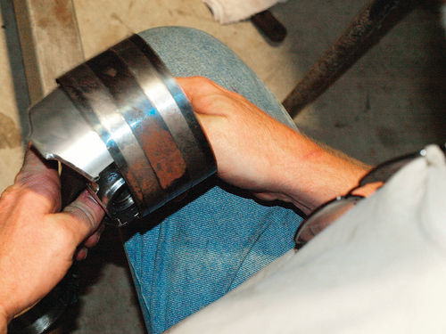
After you’ve torqued the main bearing caps, return the engine to the upright position. Install the connecting rod bearings halves to the connecting rods, reserving one of halves for the connecting rod caps once the pistons and rods are in the cylinders. Lubricate the connecting rod bearings with Vaseline. Lubricate the piston walls and rings with engine oil. Place a ring compressor around the piston to prevent the rings from damaging the cylinder walls (Photo 12). Tighten the ring compressor just enough to press the rings into their grooves on the piston.
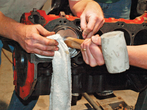
Prior to placing the connecting rod down the cylinder, attach a soft material to the connecting rod bolts (Photo 13). Examples of this would be pieces of fuel line or plastic caps. This is to protect the newly polished crankshaft and cylinder walls as the connecting rod bolts move down the cylinder wall to connect to the crankshaft. Place the piston into the cylinder. When you meet resistance, strike the top of the piston with a rubber mallet or the end of a wooden hammer to seat the piston into the cylinder (Photo 14). In the process, the ring compressor should be sliding off the piston.
Once all of the pistons are in place, attach the connecting rod to the crankshaft and torque to the required specifications.
Step 5
Install the Camshaft and Timing Chain.
Lubricate the camshaft with assembly lubricant. If your camshaft did not come with lubricant, use a high-quality assembly lubricant. Install the camshaft with the gear end to the rear of the engine.
Now it’s time to set up your timing chain. Install your crankshaft sprocket (the smaller of the two sprockets). The crankshaft sprocket has a keyway to direct your installation. Also, there’s a dot on one side of the sprocket. This dot goes to the outside of the engine (away from the block). Slide the sprocket onto the crankshaft.
To set top dead center for your number one piston, turn the crankshaft to move the top of the piston to the top of the cylinder bore. Place a dial indicator on the top of the cylinder block. When your dial indicator stops moving and then begins moving in the opposite direction, you’re close to top dead center. Move your indicator mark to the position where the needle stopped moving, continue turning your crankshaft until the needle starts moving back in the opposite direction, place your second indicator mark at that point on the dial indicator. Reverse the motion of the piston until you are in the middle of those two marks and you then have top dead center. To double-check your top dead center mark, the indicator dot on the crankshaft sprocket should be at the top.
To set the camshaft, follow your cam manufacturer guidelines. When the number one piston is at top dead center, both the intake and exhaust valves are closed. The easiest way to set your camshaft is to place the camshaft sprocket on the end of the cam. There is an indicator dot on the camshaft sprocket just like the crankshaft sprocket. To rotate your cam into its proper position, rotate the camshaft until the indicator dot on the camshaft sprocket meets the indicator dot of the crankshaft sprocket, dot to dot. This should be the position of the camshaft where both intake and exhaust valves of the number one cylinder are closed. Once this is complete, remove the sprocket from the camshaft. Loop the timing chain around the crankshaft sprocket. Making sure your dots are still in proper alignment, slide the camshaft sprocket into the chain, then onto the camshaft dowel pins. Make sure your dots are aligned, pointed at each other. Install the timing chain cover.
Step 6
Installing the Heads.
The heads for our 427 are high-flow, high-performance reproduction L88 aluminum heads. These heads came with the valves, guides and springs already installed.
Place the head gasket on the block (not the head). Be certain that the head gasket is on the correct way, that there is no overlap into the combustion chamber of the cylinder and that no water jackets are covered (Photo 15).
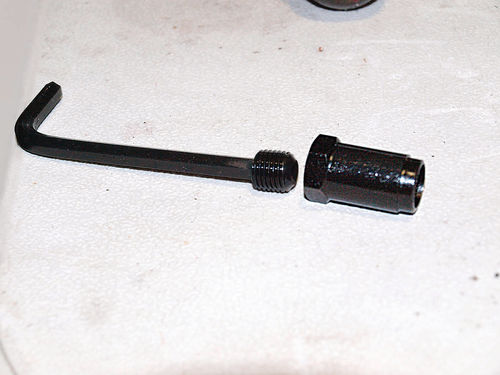
Once the head gasket is properly in place, place the head on the block. Prior to inserting your bolts, apply thread sealer to threaded ends. Head bolts come in different lengths (Photo 16). Because some of the bolts go into water jackets, the thread sealer prevents coolant from weeping out of the bolt holes. Make sure you are using the proper length bolt in each hole. (A tip: the longest bolts typically go along the middle line in the valve train.) Hand-tighten your head bolts into place. You might have to use a socket end to snug them down. Note: Compare the torque specifications of your head manufacturer, your head bolt manufacturer and the gasket manufacturer. In a perfect world, they would all be the same as on our 427. However, there are occasions when the three will not match BUT the specifications will be within 5-10 lb.- ft. Throw caution to the wind and select which spec you want to follow.
Engine blocks will have a specific sequence for torquing head bolts (Photo 17). Follow this sequence to make sure your head is properly secured to your block using a torque wrench. Repeat for the other head.
Step 7
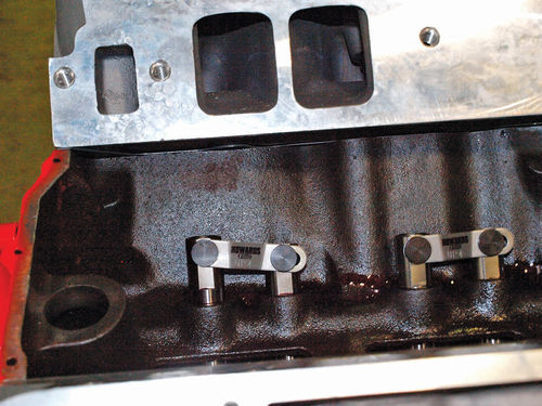
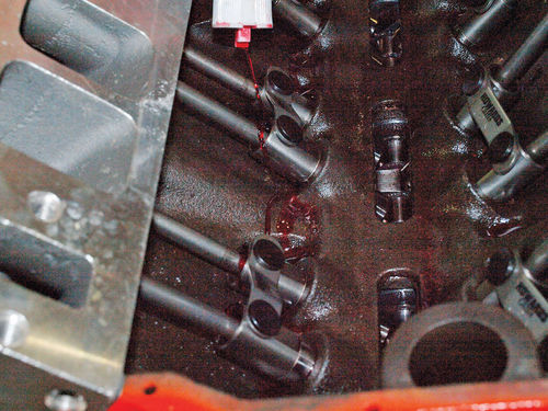
Install Lifters, Push Rods and Rocker Arms.
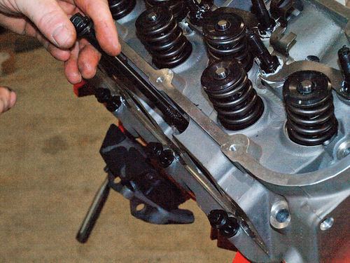
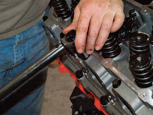
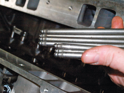
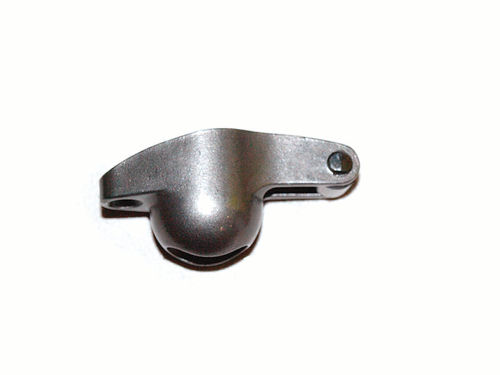
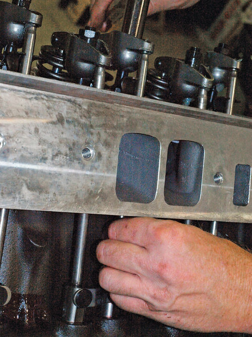
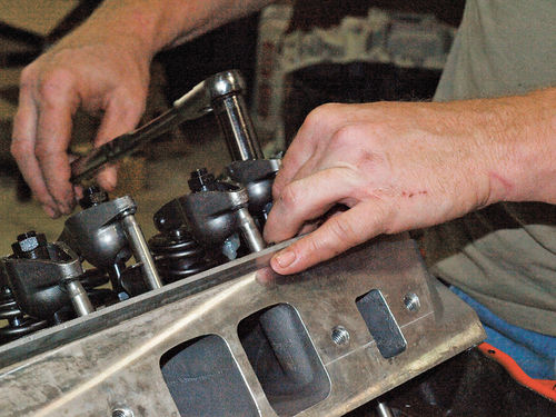
We’re almost there. This 427 will have hydraulic roller lifters and roller bearing rocker arms. As a result, there will be zero lash at the rocker arms. Lubricate the lifter bores prior to placing the lifters in with assembly lubricant (Photo 18). Place the lifters into the bores (Photo 19). Once your lifters are in place, insert your pushrods. NOTE: There are two different lengths to the pushrods (Photo 20). The longer pushrods are for the exhaust side, the shorter pushrods are for the intake side of the valve. After the pushrods are in, install your rocker arms. NOTE: Lubricate all contact areas liberally with assembly lubricant (Pho - to 21). Our rocker arms came with ball pivots (Photo 22), and perma lock rocker arm adjusters. Use an Allen wrench to remove the set screw that came with the rocker arm adjusters (Photo 23). Hand-tighten the rocker arm adjusters to secure the rocker arm into place. To set up your valve train, use a ratchet drive on the rocker arm adjusters (Photo 24). Find the lifters that are not being pushed upward by the cam. With your free hand, spin the pushrod while simultaneously tightening the rocker arm adjuster. When the pushrod stops spinning with your free hand stop the ratchet drive and continue ½-turn (Photo 25). This will pre-load the lifters. Rotate the camshaft to find the other lifters that you did not adjust previously. Repeat the above procedure. Continue this until all of your valves are adjusted.
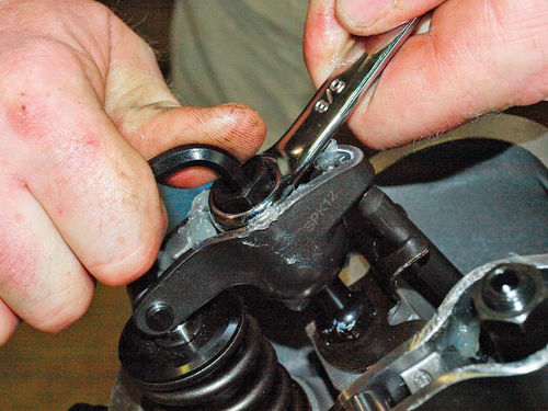
Before you tighten the rocker arms, check to make sure all of the rocker arm roller tips are sitting appropriately on the valve stems. Once your rocker arms are in place, insert the set screws and tighten with an Allen wrench while keeping the bolt heads secure with a wrench (Photo 26). NOTE: Do not tighten your rocker arm adjusters after you have performed the preload with the pushrods.
Step 8
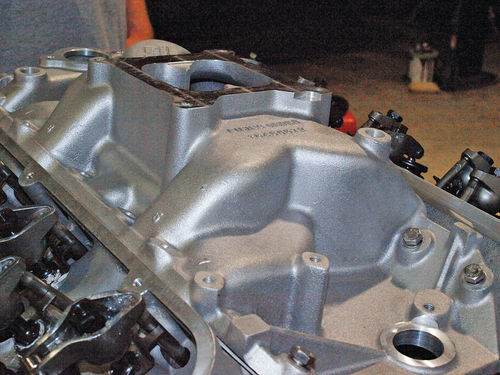
Install the intake manifold.
Once your valve assembly is complete, it’s time to install the intake manifold. Check your gaskets to make sure you have them installed in the proper direction. We applied a bit of tacking glue to the head to keep the gasket in place; apply your intake manifold gaskets. Apply an engine sealant to the front and rear block mounting areas. Place your intake manifold onto the block. Insert your manifold bolts and secure them to the block (Photo 27)
Step 9
Install the Oil pan and Valve Covers.
If you are reusing the existing valve covers, make sure that the valve cover rails are even and not warped and that all previous gasket residue has been removed. Apply a gasket sealant along the valve cover, then apply your valve cover gasket. Repeat on the other side.
Prior to installing the oil pan, dry fit the oil pan to the bottom of the block to make sure your oil pump pickup is in the proper position. Once you’ve determined the pump is correct, repeat the steps outlined above for the installation of your valve cover gaskets.
If you’re not quite ready to install the carburetor, cover the mounting area of the intake manifold with tape to keep out any foreign particles.
Now that you’re done, let’s start planning our first drive.


