All about vacuum systems in cars
VACUUM HAS BEEN an integral component in various automotive systems since the early part of this century. As time has passed the use of vacuum has increased steadily and in recent years it has grown quite dramatically. But in spite of its rather widespread use, particularly in the last three or four decades, the basic concepts involving the use of vacuum in automotive systems remain somewhat enigmatic for most people. As a result, diagnosing and repairing malfunctions in vacuum components and in systems that utilize vacuum is beyond the reach of many of us. With an understanding of automotive vacuum basics, you will be better able to analyze a rough-running engine and vacuum-powered accessories such as windshield wipers, heater, air conditioning and ventilation controls, and hideaway headlights.
The fundamental concepts underlying vacuum and how those concepts relate to the use of vacuum in automotive systems is a logical starting point. In subsequent articles we will explore the variables that can affect engine manifold vacuum, how engine manifold vacuum is measured, the use of vacuum as a diagnostic tool, how to identify problems and develop solutions for different types of vacuum maladies. We will also show you a close view of the various other components that comprise a typical automotive vacuum system.
The Basics
Technically speaking, a vacuum results when an enclosed space is devoid of all matter, including air. This is the definition of a complete vacuum. But there very frequently exists what amounts to an incomplete or partial vacuum.
Vacuum as it relates to automobiles almost always refers to partial vacuum, but we use the term to include both a complete and partial vacuum. You will never hear anyone say, “I want to install a hotter cam in my engine, but I’m afraid that it won’t make enough partial vacuum.” Likewise, no one refers to the partial-vacuum booster on their power brakes.
How Vacuum Is Measured
In the United States the standardized method for measuring vacuum is in inches of Mercury. Why, in the name of Charles F. Kettering, is that? As with many of life’s minor mysteries, the explanation of this conventional method of measuring vacuum is rather simple. Please join me on a brief journey back to 7th grade science class.
As you no doubt remember, your teacher said the earth’s atmosphere exerts a pressure of approximately 14.7 pounds per square inch on everything at sea level. Below sea level the pressure increases and above sea level it decreases. At sea level, 14.7 psi will support a column of mercury in a standard manometer gauge approximately 30 inches high. The manometer is a U-shaped tube marked incrementally and containing mercury.
A partial vacuum, by definition, exists in a container in which the atmospheric pressure is less than the earth’s atmospheric pressure given all the same variables. So if the earth’s atmospheric pressure at sea level will support a column of mercury at a height of about 30 inches, a partial vacuum will support that same column at a height less than 30 inches. In a complete vacuum, the column of mercury will not rise at all.
When the measurement of vacuum is expressed in inches of mercury, what is actually being described is the number of inches by which the given vacuum reduces the column of mercury that atmospheric pressure is capable of supporting. For example, when an engine produces 16 inches of vacuum, that engine produces enough vacuum to reduce, by 16 inches, the height of a column of mercury that atmospheric pressure is capable of supporting. In that sense, vacuum measurement in inches of mercury (Hg) is really a negative pressure measurement. However, convention dictates that we express it as a positive figure.
It is common to use the word “pull” when describing a certain amount of vacuum. For example, you may hear someone say an engine pulled 16 inches of vacuum. This is an appropriate use of the word “pull,” because 16 inches of vacuum is enough vacuum to pull a column of mercury supported by atmospheric pressure down 16 inches.
Sources of Vacuum in Cars
Vacuum that is utilized in automobiles can originate in several ways. By far the most prevalent source is the car’s engine. Vacuum is a natural byproduct of gasoline-fueled, internal-combustion engines in operation.
A vacuum results when air is withdrawn from an enclosure. But another way to create vacuum is to increase the size of the enclosure without increasing the quantity of air inside of it. An engine creates vacuum in this way.
When the piston is on its intake stroke it moves down. As this happens, the volume of the cylinder increases. The piston moves down so quickly that the incoming air/fuel mixture can not enter the cylinder fast enough to entirely fill the space created by the descending piston. What is created? A partial vacuum. It is this partial vacuum — continually created in each cylinder — that gives rise to what we call engine manifold vacuum.
A second source of vacuum utilized in some automobiles is a vacuum pump. Vacuum pumps are designed and powered in many different ways, but the most common is a mechanical diaphragm-type that is an integral part of the engine’s fuel pump.
This type of vacuum pump is a reliable device and was often utilized (along with engine manifold vacuum) to actuate vacuum-powered windshield wipers and other vacuumpowered accessories. Prior to the late 1950s, vacuum advance was used for the ignition timing via the distributor. It also is a factor in some of the early automatic and semi-automatic trans missions and overdrive units. Manifold vacuum alone was not a good source for vacuum-powered windshield wipers because manifold vacuum fluctuates considerably according to engine speed and load. In the absence of a secondary source of vacuum, the wipers would not function when manifold vacuum drops as a result of the engine accelerating rapidly or operating at high speed.
A mechanical diaphragm-type vacuum pump creates vacuum in essentially the same way that gasoline engines create it. The arm that actuates the fuel-pump diaphragm also actuates the vacuum diaphragm by means of a link that pushes the vacuum diaphragm upward (or downward in a less-common type of pump in which the vacuum portion of the pump is below the fuel portion). When the arm pushes the vacuum diaphragm up, it compresses the air in the vacuum chamber and causes a spring-loaded exhaust valve to unseat, thus expelling some of the air from the vacuum chamber. On the return stroke of the arm, a spring forces the vacuum diaphragm downward, which creates a suction in the vacuum chamber. This suction is created because as the vacuum diaphragm moves down, the volume of the vacuum chamber increases but the quantity of air inside does not. When the suction in the vacuum chamber is sufficient, it opens a spring-loaded intake valve that permits the vacuum created by the pump to be applied to the vacuum-powered windshield wiper motor or other accessories.
Diesel Engines
Since you read it earlier in this article, you may be wondering why vacuum is a natural byproduct of gasoline-fueled internal-combustion engines in operation. Why gasoline-fueled engines in particular? Because internal combustion engines powered by diesel, the only other fuel widely used in vehicles, produce little or no vacuum when they are operating.
In a gasoline-powered engine, the air/fuel mixture cannot pass through the carburetor, intake manifold, cylinder-head port and open intake-valve fast enough to fill the space created in the cylinder when any given piston moves down rapidly. While each of the impediments to air flow contributes to the creation of vacuum, most of the restriction in air flow stems from the carburetor. This restriction in air flow, at the same time that the cylinder is expanding due to the piston’s downstroke, as you now know, creates manifold vacuum.
One of the main differences between diesel and gasoline engines is the method for introducing the fuel into the cylinders. Unlike gasoline engines, diesels do not employ carburetors to introduce an air/fuel mixture into the engine. Instead, air alone (no fuel) is introduced directly into the cylinders on the intake stroke and fuel is injected into the compressed air near the top of the each piston’s upstroke. In a diesel engine the air entering the cylinders is not metered and restricted as it is from the carburetor in gasoline engines. Therefore, when each cylinder in a diesel engine increases in volume as its piston moves downward, the incoming quantity of air is usually great enough to fill the expanding cylinder and very little vacuum is created.
As a result of the inability of diesel engines to produce any significant quantity of vacuum, diesel-powered vehicles utilize vacuum pumps to provide needed vacuum. The pumps are typically mechanically actuated diaphragm-types that are driven by the camshaft, though electric-motor driven pumps have also been used.
“Normal” Engine Vacuum
The average gasoline engine in good condition produces between 16 inches and 22 inches (Hg) of manifold vacuum at idle. Certain variables, such as altitude and barometric pressure, can alter readings, but are essentially insignificant unless extreme conditions are a factor. As a general rule, a vacuum gauge will read about one inch (Hg) lower for each 1000 feet of elevation above sea level. Weather conditions that include high barometric pressure cause a vacuum gauge to read higher and the converse is equally true.
A more important variable that affects manifold vacuum is the camshaft profile. The higher the valve lift, the lower the normal vacuum reading will be. This is because a higher valve lift permits a greater quantity of air to enter into the cylinder when the piston is on its intake stroke, thus diminishing the vacuum created by the sudden expansion of the cylinder volume.
Another camshaft characteristic that affects manifold vacuum is valve overlap. The greater the valve overlap, the less vacuum. Valve overlap is the duration of the engine cycle, measured in crankshaft degrees, when a cylinder’s intake and exhaust valves are both open at the same time. Greater valve overlap reduces vacuum for the same reason higher valve lift reduces it — a greater quantity of air is permitted to enter the cylinder as the piston moves downward on its intake stroke.
Piston stroke also affects an engine’s manifold vacuum. A longer stroke generally will produce slightly more vacuum than a comparable engine with a shorter stroke.
Knowing that the majority of street-driven, gasoline-fueled automotive engines in good condition normally produce 16 inches to 22 inches (Hg) of vacuum at idle, and taking into account all of the variables that will affect a manifold vacuum reading in a properly running engine, you can come up with a guesstimate as to what “normal” vacuum should be for your engine. Camshaft profile is usually the most significant influence and the effect of the cam profile is easy to determine, if you know what that cam profile is. Check the specification card that came with the cam when it was new if you’ve replaced the cam) or refer to the service manual on your vehicle if the cam is original equipment.
If you do not know the specifications for your cam, but because of the way your engine idles you suspect that they are far from stock, you can measure your engine’s actual valve lift and overlap. An experienced cam-grinder or knowledgeable engine-builder can tell you approximately how much manifold vacuum should be produced by a cam with the measurements you made.
Using A Vacuum Gauge
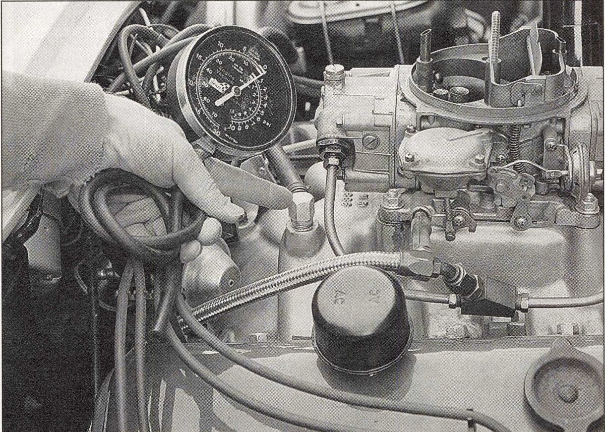
A vacuum gauge is the easiest tool to measure manifold vacuum. Most gauges are small enough to fit in the palm of your hand and have a dial face with markings in one-unit increments that usually range between 0 and 30. The gauge is calibrated so each unit on the face correlates to a vacuum force sufficient to move mercury one inch in a standard manometer.
A vacuum gauge has a port through which you must route the vacuum that you seek to measure. The easiest way to do this is with a length of rubber hose that connects the gauge to the source of vacuum. To measure an engine’s manifold vacuum, connect the gauge to your engine’s intake manifold via a nipple threaded into a tapped port in the manifold. Most intakes were manufactured with threaded ports to provide a reliable source of manifold vacuum for power brakes and other vacuum-powered components. Even if your car is not equipped with power brakes or other vacuum-powered parts, the hole is usually in the intake manifold with a pipe plug closing it.
The vacuum gauge hose must connect to a nipple in order to get a reading. Sometimes there is already a nipple that allows a hose to connect the manifold to the brake booster. Sometimes there are multiple ports that allow connection to other parts such as air conditioning, hideaway headlights, automatic transmission, smog controls or others. If you need to measure engine vacuum in order to analyze the condition of the engine (rather than the accessories) isolate the engine by plugging any vacuum lines that come off the engine to power accessories.
There may be occasions when you want to keep the entire vacuum system intact when you measure manifold vacuum. For example, when you search for a vacuum leak begin the analysis by measuring the engine’s vacuum output when it is isolated and then measuring it when the entire vacuum system is connected. If you want to measure manifold vacuum with the system connected, you should remove one of the factory vacuum hoses routed to the intake, insert a short length of new hose with a “T” fitting onto the nipple, reconnect the factory hose you removed onto one port of the “T” fitting, and then connect your gauge to the other port of the “T” fitting.

If your intake has a vacuum port hole Gt will be smaller than the temperature sender port) with a pipe plug closing it off, remove the plug and install a fitting with a nipple that allows you to connect your vacuum gauge. Don't forget to reinstall the plug when you are finished or you will have a vacuum leak out the open nipple.
In the absence of a hole directly in the intake manifold, you can usually access manifold vacuum from a port in the carburetor. Always remember, however, that for the carburetor port to provide manifold vacuum, it must open into the intake manifold below the throttle plate in the carburetor. Carburetors are frequently equipped with vacuum ports above the throttle plate that supply vacuum to EGR valves, vacuum-advance mechanisms on distributors and other devices that need manifold vacuum when the engine is under load or operating at high speed but must not have any vacuum at idle. These ports above the throttle plate cannot be used to accurately measure manifold vacuum. The best way to determine if a particular port in your carburetor is above or below the throttle plate is to remove the carburetor and examine it. It is sometimes helpful to snake a very thin piece of wire (like piano wire) down a port in question and observe where the wire exits.
In case your vacuum test indicates your engine is not producing a steady reading of 16 to 22 psi, next month we will explore methods in which vacuum can be used to diagnose the condition of an engine.


